
Mold Design with 3D Scanning and Reverse Engineering
21st Oct 2021
Reverse engineering refers to the process of extracting design elements from an existing finished system or a mostly industrially manufactured product by examining its structures, states and behaviors. Basically an exact technical plan is derived from the object data acquired. In contrast to a functional recreation, reverse engineering aims to reproduce the existing object as accurately as possible. In order to verify the insights gained, an attempt is often made to produce a 1:1 copy of the object, on the basis of which it is possible to carry out further development. Infamous for its reputation of empowering theft of intellectual property and copyright, the attitude towards Reverse Engineering in any industry is quite ambivalent. But the opportunities it opens up for mass customization and product design especially in the mold industry are undeniable.
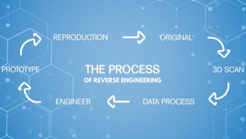 The Process Workflow of Reverse Engineering
Generation of CAD data of the mold via 3D scanning of the part
The first step of digitization in molding is 3D scanning of the component for tooling. Professional and inexpensive digitizing of components has become possible for everyone with little effort and a 3D scanner. 3D data can be easily captured on site and users benefit from very fast run times, low cost, efficient handling and easy communication.
The processing of the 3D scan data into CAD data
The second step in digital molding tooling is the conversion of the point cloud generated in the 3D scan into CAD/CAM capable data. The processing of the STL data produced by the 3D scanner can then be reconstructed in CAD. The characteristics of the part can be recognized based on the scan points and these points can be replaced with CAD capable surfaces. This process is called surface reconstruction. With the finished data of the CAD/CAM solid model, tooling molding can start immediately.
Mold Measuring with 3D Inspection
Traditional mold measuring methods are generally done manually using contact measuring tools such as vernier measuring tools or micrometers. Only a few attributes such as mold width, height, and depth can be measured, while the curvature of the surfaces and sunken surfaces are difficult to measure. These measuring methods are not only complicated and time consuming, but it is also difficult to ensure measuring quality and accuracy of large-size molds, making mold measuring a very time-consuming and laborious part of industrial manufacturing.
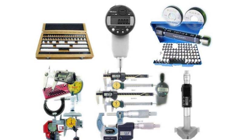 Traditional measuring tools.
Image source: Baidu
For this reason, non-contact 3D scanner measurement is gradually becoming one of the main methods of industrial mold measuring due to its abilities of overcoming the deficits of traditional measuring methods and achieving high-quality inspection which is vital to guarantee a long term fluent production of high quality identical molded products.
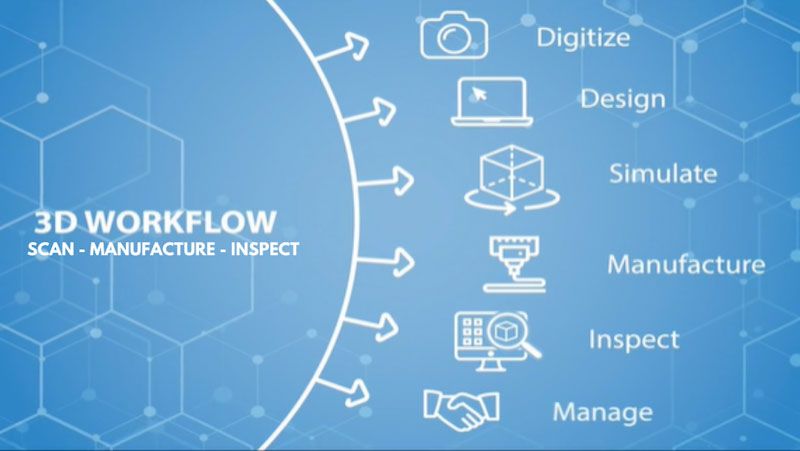 The Digital Manufacturing and Inspection Workflow
There exists a wide array of 3D inspection tools powered by different scanning technologies aiming at different inspection requirements. In this article several projects using different technologies are shared in order to demonstrate the wide array of possibilities these devices can be applied in.
High Precision Inspection with Blue Light Metrology 3D Scanning
“Blue light technology recognizes contour by triangulating the line of sight of a photographic lens and the line of sight of a light source that projects a “fringe” pattern onto the surface being measured and then uses software to convert multiple images into a three dimensional representation.”
–K.R. Srinivas, Qualitymag.com
Blue Light Metrology 3D scanning technology is able to precisely capture small and filigree details of tiny to medium sized objects rigidly requiring persistent performance in their product lifecycle.
Nut inspection with OptimScan 5M
Nuts are an integral part of everyday life. All sorts and kinds of products and fixtures require strong and stable nuts. Usually nuts are casted and then processed to the final product. The characteristics of the casted nut directly affect the nut and bold assembly performance which is vital for the reliability, strength and stability of the installation or product it is screwed in. So quality control of the molds which are used for casting the nuts is essential to maintain high quality and security of the product. Blue light 3D scanning technology can help significantly to inspect the dimensions of the nut assembly and thus ensure accurate maintenance of the molds.
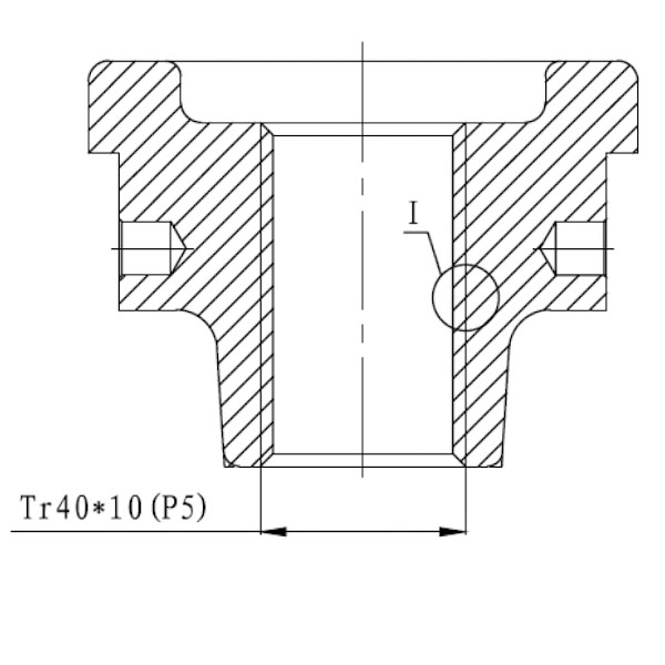
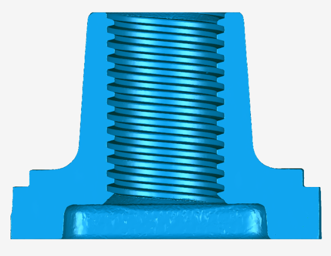
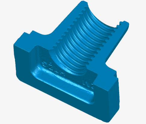
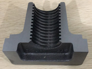 Mold for nut casting
Measurement requirements:
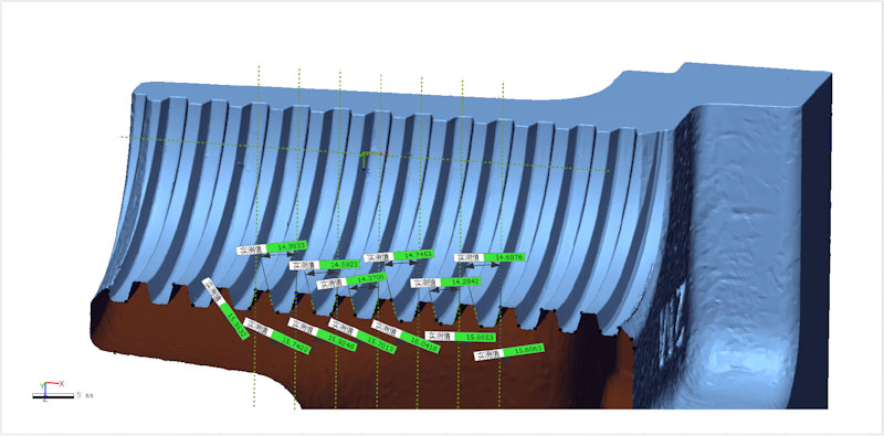
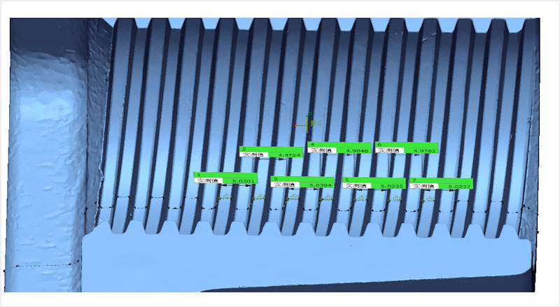
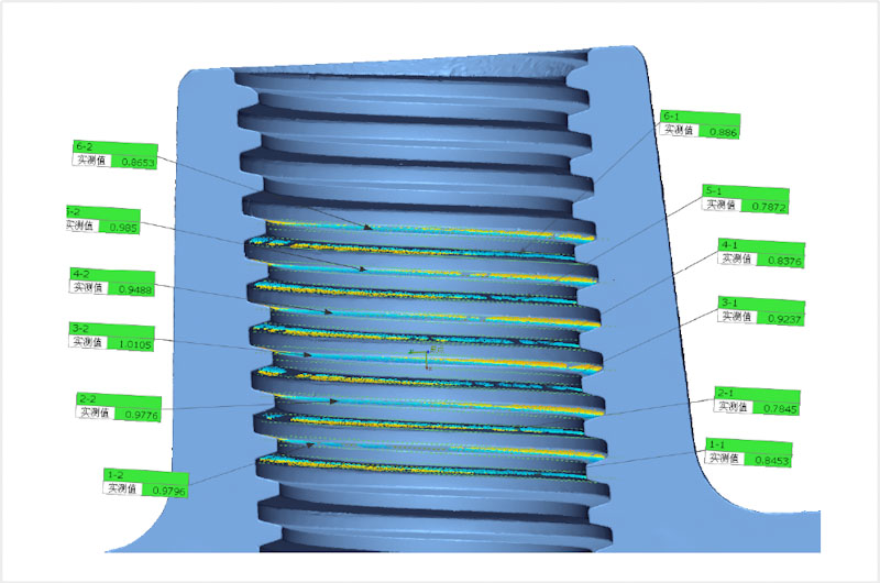
Measurement of key dimensions according to the drawing. The pitch directly affects whether the bolt and nut will fit together. The half-angle (15° angle) of the threaded crescent will affect the fit of the nut and bolt tooth pattern and the consistency of the flatness of the tooth profile affects the degree of surface engagement of the bolt and nut, i.e. whether it can be tightened or not.
Conventional measurement methods are inconvenient due to the spiral arrangement of the teeth. It takes half a day to measure one product and thus is obviously extremely inefficient.
Recommended measuring device:
OptimScan 5M Blue Light Metrology 3D Scanner
The 3D data of the nut is captured by OptimScan 5M and then imported into a measuring software. The advantages of such software lies in the freedom for measurement. There are no shape restrictions and cross-sections can be easily measured after 3D data acquisition. Let´s take a look at the measurement process:
1) Acquisition of 3D point cloud data by 3D scanning
2) Import data into the measurement software and coordinate alignment
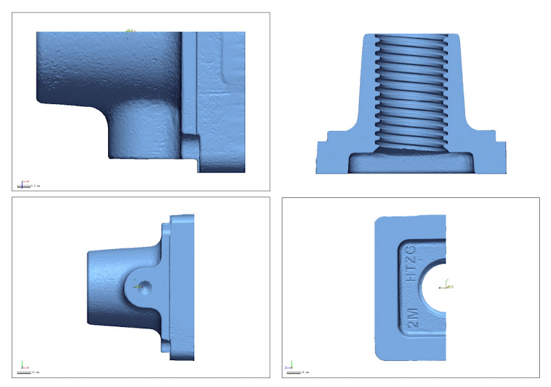 Scan data coordinate alignment
3) Measurement of the pitch and profile by making a two-dimensional cross section; measurement of the nut I.D. and profile flatness by creating cylindrical features and planes.
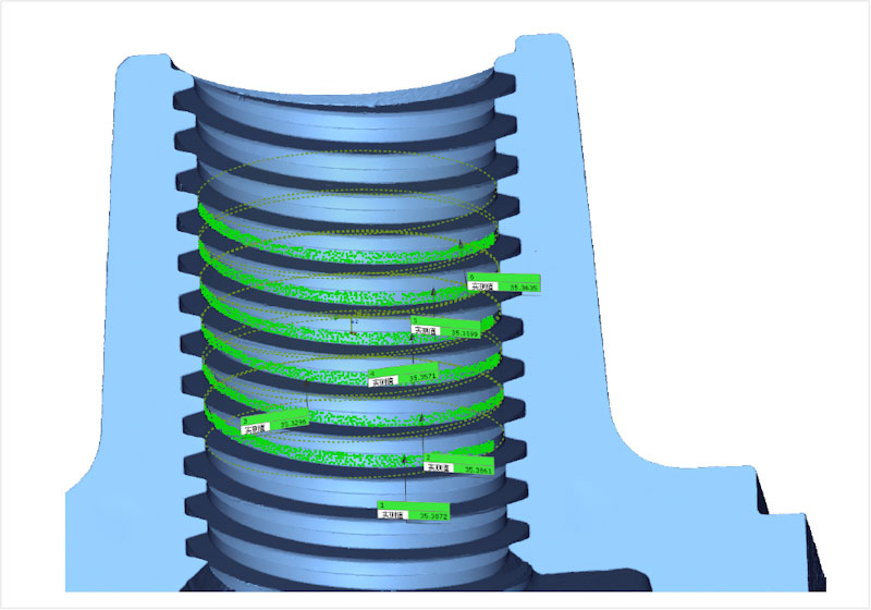
The measurement accuracy of OptimScan 5M can account up to 0.01mm, thus guaranteeing highly precise measuring results. Thanks to the high efficiency of modern technology, scanning and measuring can be completed within one hour.
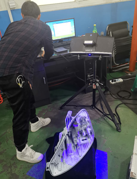
Full-size 3D inspection of automobile lamp housings with OptimScan 5M
Measurement requirements: 3D full dimensional inspection of automotive lamp housings
The deviation caused by processing is not only a human factor, but also caused by temperature and humidity hugely affecting the accuracy of the product; the out-of-tolerance dimension affects the assembly of lights and related parts, and the detected out-of-tolerance parts need to be corrected according to the requirements in order to meet the assembly requirements. Therefore, it is a key step of product quality control to conduct three-dimensional full dimensional measurement of the processed workpiece.
Traditional inspection methods: traditional inspection with calipers, micrometers and coordinate equipment aiming at establishing a coordinate system to measure in a step-by-step manner; the difficulty of contact measurement is easy-to-cause deformation of the workpiece. Furthermore it is difficult to establish coordinate systems for irregular workpieces.
Recommended measuring device:
OptimScan 5M Blue Light Metrology 3D Scanner
The whole 3D data of the lamp housing is acquired with OptimScan 5M and then imported into the measuring software.
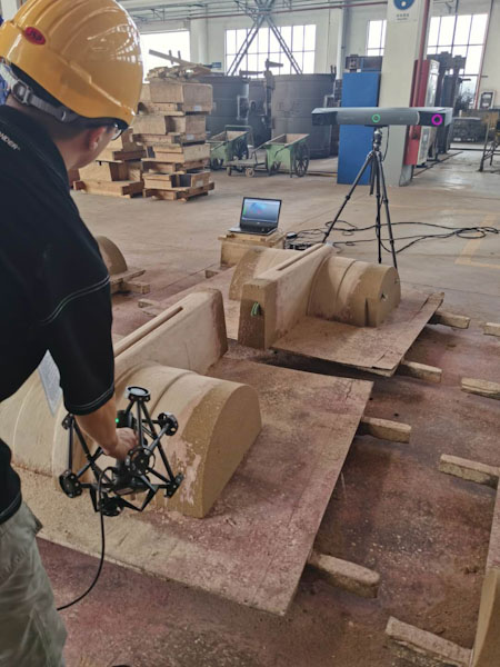
1) Acquisition of 3D point cloud data of headlights through 3D scanning.
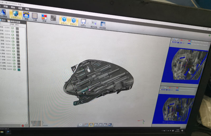 Scan Software Interface
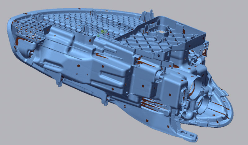 Scan Data
2) Import of the scan data and CAD data into the measurement software, alignment of the coordinates, and generation of 3D deviation chromatogram
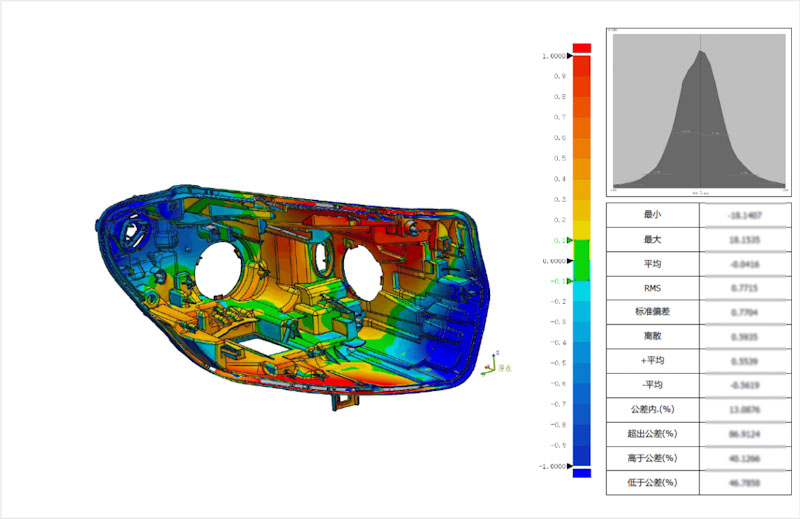 3D chromatographic analysis
3)Performance of full-size measurements
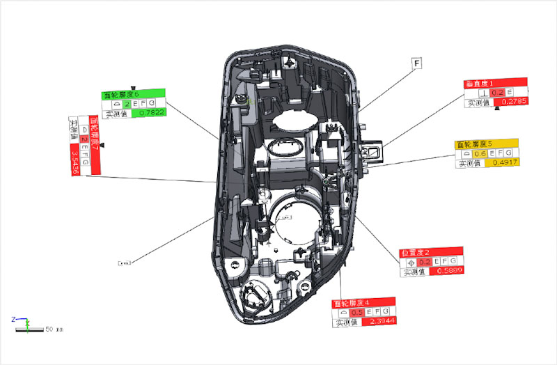 Full size measurement
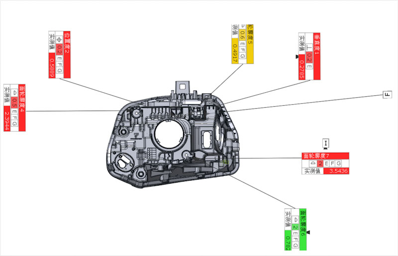 Full size measurement
The fast access to the 3D scanning data and the immediate capacity of full size measurement of the data is a huge advantage of the whole process. The high measurement accuracy, up to 0.01mm and the fast and efficient data capturing and software processing helped to complete the whole digitizing and measuring task in three hours.
Large Scale Inspection with Optical Coordinate Measuring
“Coordinate measuring machines are used to verify the dimensional accuracy of components with very high precision. This makes them an important tool in production measurement technology and thus in quality assurance, especially in innovative industries such as mechanical engineering, automotive or aerospace.”
– Fraunhofer Institute of Physical Measurement Techniques (IPM)
Optical Coordinate Measuring has paved the way to fast, efficiently and foremost accurately digitizing large size physical object flexibly and at ease. Businesses aiming to enter the era of quick and precise 3D digitization of a great variety of different objects for the purpose of reverse engineering and inspection in industrial demanding environments can hugely benefit from the advantages of optical coordinate measuring compared to state of the art tactile coordinate measuring machines.
Virtual assembly analysis of a sand mold´s wall thickness with FreeScan Trak
Measurement requirements:
measuring the thickness inside the cavity of a sand mold
Conventional measuring method:
Using a card plate or scribing method to measure. Because the upper and lower die are separated, it is impossible to accurately measure the thickness of the entire mold cavity.
The 3D data of the sand pattern and sand core is acquired with FreeScan Trak Optical Coordinate Measuring System. The assembly of the upper and lower mold can be carried out at ease in the software, and the thickness inside the cavity can thus be measured quickly and efficiently.
Scan time:
20 minutes
Measurement time:
20 minutes
1) Acquisition of 3D point cloud data by means of 3D scanning.
2) Using feature alignment in the inspection software, the sand core and sand pattern are assembled separately, and then in the same way, the assembled core is placed inside the sand pattern to simulate the actual field assembly state.
3) Wall thickness analysis by means of inspection software
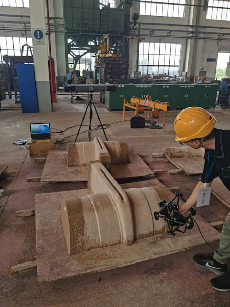
Fast and convenient Digitization & Inspection with Hybrid Light 3D Scanning Technology
The advantages of LED and laser, boosting the adaptability of scanning materials and ambient light to another dimension, and predestining the device for demanding industrial applications are united in the EinScan HX. In rapid scan mode, blue LED structured light is used for capturing object data. 3D data can be obtained quickly without having to apply reference points. The laser scanning mode is equipped with multiple blue laser lines ensuring high accuracy and enabling 3D scanning of reflective metal surfaces quickly, providing high-quality 3D data for reverse design, CAD/CAM and 3D printing.
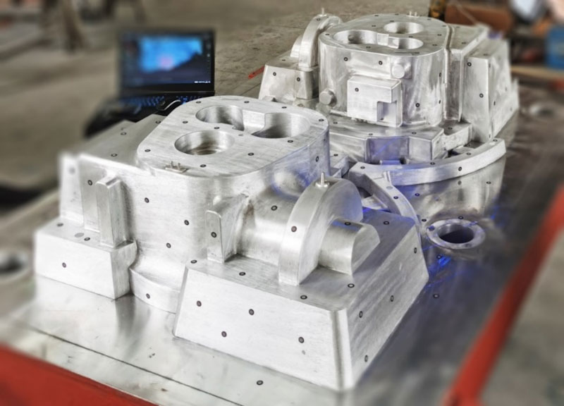
A mold factory made a 1.5m×1m aluminum mold according to customer needs. Due to the significant differences in processing equipment and technology, in many cases the mold cannot reach the required accuracy after production. For this reason, mold measuring becomes a necessary stage in the manufacturing process of industrial products.
On account of the large size of the aluminum mold, the traditional manual measuring tools are not able to obtain the comprehensive data information of the mold accurately. In order to improve the current dilemma of poor measuring results and inefficient measuring work, the mold factory chose to use a handheld 3D scanner to perform 3D measurement of the mold.
Measurement and inspection process
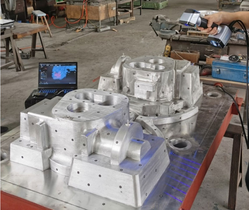
For this measuring process, the mold factory chose EinScan HX dual blue light handheld 3D scanner. Due to the integration of blue laser and blue LED light source in one device, EinScan HX is compatible with various application scenarios in measuring. Due to its portability, user friendly handling and high scan speed, the complex working environment of the factory is no longer a complicated obstacle during the measuring process, but a challenge excitedly accepted by EinScan HX bringing great improvements to the efficiency of quality measuring.

Step 1: Application of Reference Points
For this scan the laser scan mode of EinScan HX was selected. Before scanning, reference points were applied on the reflective aluminum mold workpiece.
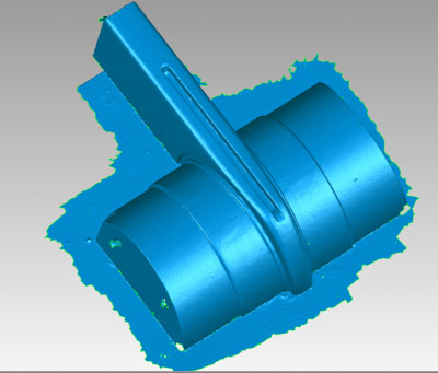
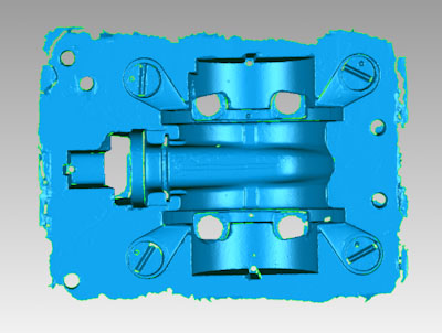
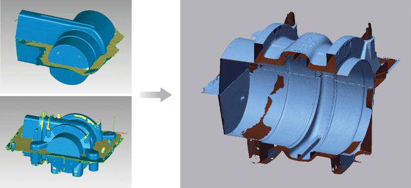
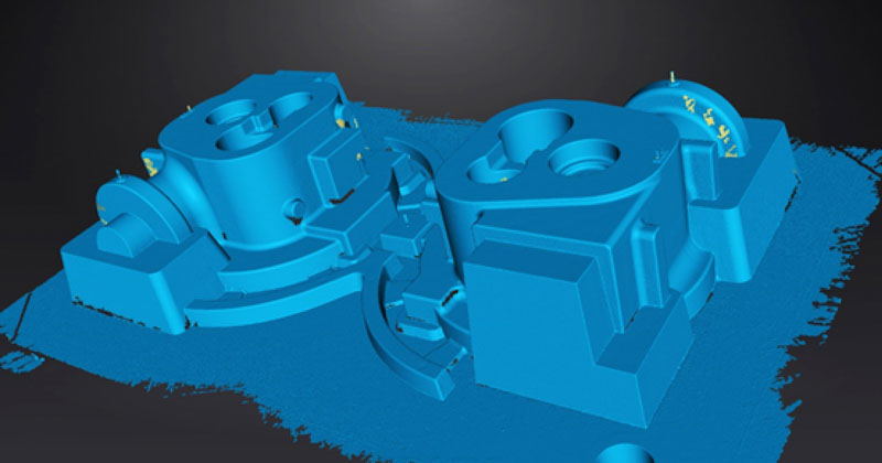
Step 2: 3D scanning
The laser mode has a scanning speed of 480,000 dots/sec. The technician spent only 10 minutes to obtain the complete high-precision 3D model data of the aluminum mold directly.
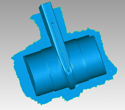
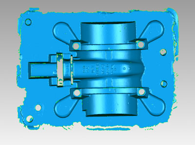
Step 3: 3D measuring
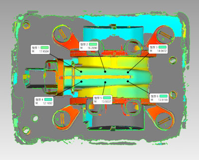
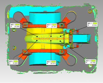
In order to check whether the aluminum mold meets the accuracy requirements, the scanned aluminum mold data and a digital model of the original design were imported into the measuring software Geomagic Control X. After the coordinates were aligned, the deviation comparison analysis was performed using the chromatogram to obtain the annotated deviation diagram. Finally the measuring report could be exported.
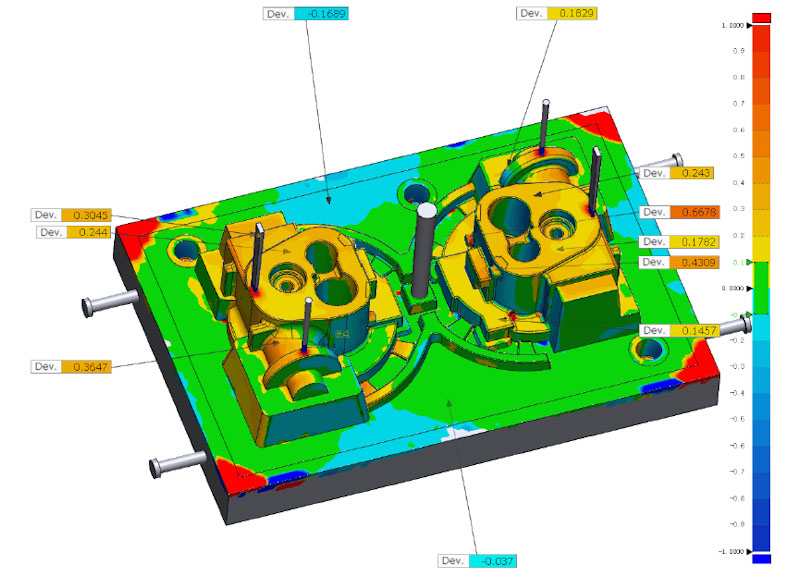
The scanning process took less than 30 minutes from applying reference points to 3D scanning to obtaining the final comparison analysis report. This method saved a lot of time in relation to traditional measuring methods and solved many parametrical problems, which cannot be detected by traditional measuring tools.
How to identify your 3D scanning requirements as a mold maker?
How
It can be quite a long and challenging journey to find the 3D scanning and measurement device to meet your needs. But the advantages of the technology and its capacities fostering efficient time and process management as well as high precision compared to traditional measuring methods has already proven valid today and will become increasingly relevant in the future. SHINING 3D offers a broad palette of 3D scanning technologies for all kinds of applications and different budgets helping users to enhance and upgrade their daily working life sustainably.