
How to Scan Deep Holes, Recesses, and Difficult Geometry
24th Aug 2026
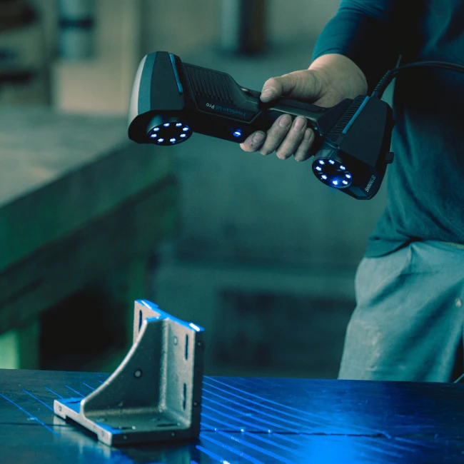
Some of the most challenging areas to capture with a 3D scanner are often relatively small: deep holes, recessed pockets, narrow slots, sharp internal corners, and undercuts.
These features are common on machined parts, castings, automotive components, molds, brackets, housings, tooling, and industrial assemblies. The majority of a part may scan easily while a handful of recessed features require much more attention.
The challenge usually comes down to visibility. Optical 3D scanners need to project light onto a surface and observe that surface with one or more cameras. Once geometry becomes deep, narrow, or partially obstructed, the scanner has fewer useful viewing angles.
Understanding that limitation makes difficult geometry much easier to approach.
Why Recessed Geometry Is Difficult to Capture
A broad exposed surface gives the scanner a clear view of both the projected light and the reflected pattern coming back from the object.
A deep hole is different.
As the opening becomes narrower and the feature becomes deeper, the surrounding walls begin to block the scanner's view. The scanner may capture the entrance and upper walls clearly while struggling to see the bottom or far side.
This is why moving the scanner closer does not necessarily solve the problem.
If the scanner is already within its intended working range, the limiting factor is often the angle at which the projected light and cameras can see the feature.
The solution is usually to improve visibility rather than simply reducing the distance between the scanner and the object.
Approach the Feature from Multiple Angles
Instead of holding the scanner directly in front of a recessed feature, gradually change your viewing angle as you work around it.
For a circular hole, for example, scan across the opening from several directions. Each position gives the scanner a slightly different view of the internal wall.
The same technique applies to pockets, slots, internal corners, and recessed mounting features.
Small, controlled changes in angle are generally more effective than large movements. You also want enough previously captured geometry or markers to remain visible so the scanner can maintain its position while you concentrate on the difficult area.
The live scan preview is particularly useful here. If a surface is not appearing in the scan, repeatedly passing over it from the same position is unlikely to help. Change the angle and watch whether additional geometry begins to appear.
Use the Right Scanning Mode
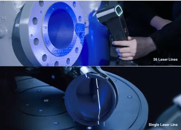
Many professional laser scanners offer several laser configurations because the same pattern is not ideal for every part of an object.
A wide crossed-laser pattern is excellent for rapidly covering large surfaces. For narrow pockets and deep holes, however, a more focused pattern can be much more effective.
SHINING 3D specifically uses single-line laser modes for deep-hole and pocket scanning across several of its FreeScan systems. The narrower projection gives the scanner better access to geometry that is difficult to reach with a large crossed-line pattern.
That does not mean you should scan the entire part using a single laser line.
A more efficient workflow is to capture the main body of the object using a fast multi-line mode, then switch to the detail or single-line mode for the handful of areas that actually require it.
Some SHINING 3D systems also include dedicated deep-hole optimization when single-line scanning is selected.
Establish Good Tracking Before Entering the Recess
Deep features can also create tracking problems.
A smooth cylindrical bore or repetitive internal structure may contain very few recognizable geometric features. If you begin scanning directly inside that area, the scanner may struggle to determine its position.
Instead, start on the surrounding surface.
Capture enough of the nearby geometry to establish stable tracking, then gradually move toward the recess while keeping some of that previously captured area within view.
If tracking becomes unstable, return to a known section of the scan and approach the feature again from another angle.
This is often much more reliable than trying to recover tracking while the scanner is pointed directly into a featureless hole.
Use Markers When the Geometry Does Not Provide Enough Reference
Reflective markers can make difficult mechanical parts much easier to scan, particularly when the object contains smooth, repetitive, or symmetrical geometry.
Markers provide known reference points that allow the scanner to maintain alignment even while the viewing angle changes.
They should generally be placed in a random pattern rather than in straight rows or repetitive arrangements. SHINING 3D's own preparation guidance recommends distributing markers randomly and keeping several visible within the scanner's working area.
For deep features, placing markers around the surrounding surface can give the scanner a stable reference while you tilt it toward the opening.
The markers do not make an invisible surface visible, but they can make it considerably easier to maintain tracking while you search for a better viewing angle.
Pay Attention to Surface Material
Recessed geometry becomes considerably more difficult when the material itself is challenging.
Dark surfaces can return less usable scan data, while highly reflective finishes can redirect projected light away from the scanner's cameras. Inside a recess, where viewing angles are already limited, these effects can become even more noticeable.
SHINING 3D recommends washable or vanishing scanning spray for transparent, shiny, reflective, and particularly challenging black reflective surfaces when necessary.
Creating a temporary matte surface can help the scanner collect more consistent data from material that would otherwise be difficult to read.
Laser scanners designed for dark and reflective surfaces may reduce the need for preparation, so whether spray is necessary depends on the scanner, material, geometry, and required data quality.
Adjust Brightness Carefully
Scanner brightness or exposure settings can also help when moving between bright exposed surfaces and darker recessed areas.
The important point is not simply to increase brightness as much as possible.
SHINING 3D's FreeScan documentation notes that brightness should be adjusted until scanned data and markers are clearly visible and complete, while setting it too high can increase noise.
Make gradual adjustments while watching the live data.
If the recessed surface begins filling in without significantly increasing noise on the surrounding geometry, the adjustment is helping. If the scan becomes unstable or noisy, back the setting down and try improving the scanner angle instead.
Slow Down Where the Geometry Gets Difficult
You may be able to move quickly across the broad exterior of a mechanical part, but recessed features benefit from more controlled movement.
Slowing down gives you time to watch the live scan, adjust the angle, and identify which portions of the feature still need additional coverage.
The goal is not simply to spend more time pointing the scanner at the same surface.
Instead, move deliberately and use the feedback from the software to determine whether each new position is actually adding useful data.
Once the feature stops filling in, change your approach.
Reposition the Part When Possible
Sometimes the easiest way to capture difficult geometry is to change the orientation of the object.
A recess facing downward may be frustrating or impossible to reach from the original setup. Rotate the part so that the same feature faces outward or upward and the scanner may suddenly have a much clearer line of sight.
This is especially useful for components that contain important geometry on several sides.
Rather than trying to capture everything during one continuous scan, you can scan the accessible surfaces, reposition the object, capture the remaining areas, and align the scan projects afterward.
When doing this, make sure the separate scans contain enough common geometry to produce a reliable alignment.
Do not capture only the missing feature. Include surrounding surfaces, edges, holes, ribs, or other recognizable geometry that appears in both projects.
Undercuts Need a Clear View
Undercuts present a slightly different version of the same visibility problem.
The surface may not be located deep inside a hole, but another part of the object physically blocks the scanner's view.
No optical scanner can measure a surface that neither the projected light nor the cameras can reach.
The only real solution is to find another viewing direction.
That may mean scanning from underneath the object, approaching from the side, or repositioning the part entirely.
For complex components, several overlapping passes from different orientations may be necessary before the undercut is fully represented.
Internal Corners and Narrow Features
Sharp internal corners can also produce incomplete data.
The scanner may capture both surfaces forming the corner while leaving the deepest part of the intersection poorly defined.
Approaching the corner from both directions usually gives better results than attempting to capture it straight on.
A focused laser mode can also help with narrow internal features.
If the data will be used for reverse engineering or inspection, review these areas carefully before meshing. A finished mesh can sometimes make a poorly captured corner look more complete than the underlying measured data actually is.
Do Not Force Every Feature into the Scan
There are practical limits to line-of-sight 3D scanning.
Very deep bores, extremely narrow passages, complex lattice structures, and completely enclosed internal geometry may simply be inaccessible to an optical scanner.
SHINING 3D's own documentation identifies lattice structures containing many small deep holes as particularly unsuitable for several handheld scanning workflows.
In those situations, another measurement method may be required.
Depending on the application, that could include conventional gauges, contact measurement, a coordinate measuring machine, or CT scanning.
The goal should not be to force a 3D scanner to perform a measurement it physically cannot see. It should be to use the scanner where full-surface optical measurement offers the greatest advantage.
Example: A Machined Part with Deep Bolt Holes
Consider a machined housing with several recessed bolt holes.
The exterior surfaces and overall shape can usually be captured quickly using a multi-line scanning mode.
Once the main geometry is established, switch to a focused or single-line mode and work around each hole individually.
Approach the opening from several angles while keeping the surrounding face and markers visible for tracking. If the surface is particularly dark or reflective, adjust the scanner settings or apply scanning spray if appropriate.
The scanner may not need to measure every millimeter of the bore for the scan to remain useful.
For some reverse-engineering workflows, accurately capturing the opening, diameter, orientation, and surrounding geometry provides enough information for the intended hole to be reconstructed parametrically in CAD.
That decision should be based on what the finished model actually needs to accomplish.
Example: Automotive and Fabricated Components
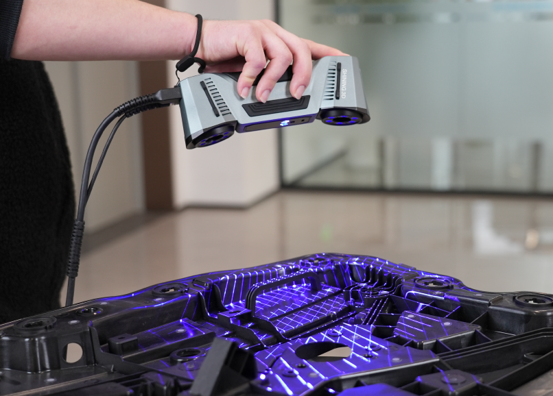
Automotive and fabricated parts often combine large easy-to-scan surfaces with recessed mounting areas, narrow brackets, holes, bends, and difficult internal corners.
Rather than slowing the entire project down, capture the main surfaces in a high-speed mode first.
Then return to the mounting points and other critical geometry with a more focused scan mode.
Markers can provide additional tracking stability around areas with simple or repetitive geometry, and repositioning the component may provide much better access to surfaces that are hidden from the original orientation.
This approach keeps the majority of the scan fast while still giving critical features the attention they require.
Example: Molds and Castings
Molds and castings are another good example of why it is useful to change scanning techniques throughout a project.
A single component may contain broad exterior surfaces, machined areas, deep pockets, ribs, draft angles, narrow channels, and sharp internal transitions.
Trying to capture all of that geometry with one scanning mode is rarely the most efficient approach.
Use high-speed scanning for broad surfaces, detail scanning where additional definition is required, and single-line scanning for recessed geometry that needs greater access.
The objective is not to find one setting that works everywhere. It is to use the most appropriate scanning method for each section of the part.
A Better Workflow for Difficult Geometry
The most reliable approach is to establish good tracking on easy geometry before moving toward the difficult area.
Keep the scanner within its intended working range, approach recessed features from several directions, and switch to a focused laser mode when a broad pattern can no longer reach the geometry effectively.
If tracking becomes unreliable, add markers or return to a previously captured section. If the surface itself is causing problems, adjust brightness or use appropriate surface preparation. If the geometry remains inaccessible, reposition the part rather than continuing to scan from an angle that cannot see it.
Finally, inspect the captured data before meshing.
A minute spent checking a difficult feature while the scan is still active can prevent considerably more work later during reverse engineering, inspection, mesh repair, or 3D printing.
Conclusion
Deep holes and recessed geometry are challenging because optical 3D scanning ultimately depends on visibility.
Better results come from giving the scanner a clearer view rather than simply spending more time scanning the same area.
Changing angles, using the appropriate laser mode, maintaining reliable tracking, preparing difficult surfaces when necessary, and repositioning the object can all improve the amount of real measured geometry you capture.
And when a feature simply cannot be seen, recognizing that limitation is just as important.
With the right workflow, many parts that initially appear difficult to scan can still be captured efficiently while preserving the geometry that matters most for the final application.