
How to Get Cleaner 3D Scan Data Before Meshing
25th Aug 2026
A good mesh starts with good scan data.
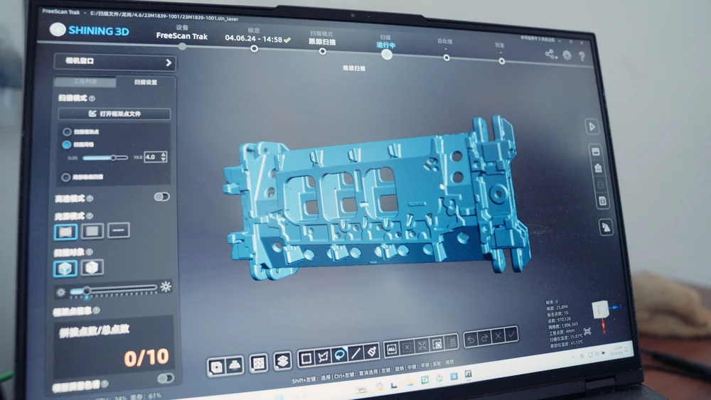
It is easy to focus on meshing settings, smoothing, hole filling, and cleanup tools at the end of a project, but many of the problems that appear in a finished mesh actually begin much earlier. Poor tracking, excessive background capture, unstable exposure, incomplete coverage, moving objects, and unnecessary duplicate data can all make the final model harder to process.
The cleaner the raw scan is before meshing, the less work the software has to do afterward.
Whether you are scanning for reverse engineering, inspection, 3D printing, archiving, or visualization, taking a few extra steps during capture can produce cleaner surfaces, reduce processing time, and give you a much better starting point for the final model.
Start with a Stable Object
Before scanning begins, make sure the object itself is not going to move.
Even small movement can introduce misalignment between frames. On a rigid mechanical part this is usually easy to control, but lightweight components, flexible materials, hanging objects, and parts sitting loosely on a table can shift as you move around them.
Secure the object whenever possible.
If you are using a turntable, make sure the part is balanced and does not wobble as the platform rotates. If the scanner will be moving around the object instead, place it on a stable surface and avoid touching or repositioning it while the scan is active.
For larger objects, also pay attention to anything attached to them. Loose cables, fabric, trim pieces, doors, panels, or other movable elements can all create inconsistent geometry if they shift during capture.
A stable object gives the software a much cleaner foundation for alignment.
Clean the Surface Before You Scan
Dust, grease, fingerprints, loose debris, and reflective contamination can all affect scan quality.
A surface that looks acceptable by eye may still produce inconsistent data under projected light.
Before scanning, remove anything that does not belong on the final model. Clean loose dirt and debris, wipe down oily surfaces, and make sure temporary objects are not blocking important geometry.
This is especially useful for mechanical parts, automotive components, tooling, and parts that have been sitting in a workshop environment.
The goal is not to make the object cosmetically perfect. It is simply to make sure the scanner is measuring the part itself instead of dust, loose material, or temporary contamination.
Use Surface Preparation Only Where You Need It
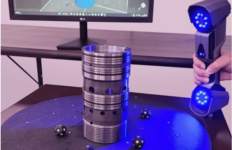
Black, glossy, reflective, or transparent materials can create noisy or incomplete data.
If the scanner is struggling to read the surface, a removable scanning spray can create a more consistent matte finish and reduce the amount of cleanup required later.
The important thing is not to coat every object automatically.
Modern laser scanners can often capture dark and reflective materials without spray, and unnecessary preparation adds time to the project. Instead, start by testing the surface.
If the live scan is clean and stable, continue without preparation.
If you are seeing excessive noise, inconsistent data, or missing areas, then consider treating only the difficult sections.
For dimensional work, also keep in mind that any physical coating adds thickness to the surface. If accuracy is critical, use a suitable thin scanning spray and account for the application where necessary.
Establish Strong Tracking Early
Clean geometry depends heavily on stable tracking.
If the scanner loses its position and incorrectly relocalizes, the resulting data may contain doubled surfaces, shifted geometry, or sections that no longer align correctly.
These problems are much harder to fix after the fact.
Begin the scan on an area with recognizable geometry whenever possible. Edges, holes, corners, ribs, texture changes, and other distinct features give the software more information to work with.
Avoid starting on a large smooth panel or repetitive surface unless the scanner is using markers or another reliable tracking method.
Once tracking is established, move gradually into more difficult areas.
If the scanner loses tracking, return to a previously captured section and allow it to relocalize before continuing.
Do not keep moving while the software is uncertain about its position.
Use Markers When They Will Improve Stability
Markerless scanning can be extremely convenient, but it is not always the cleanest option.
Large flat panels, symmetrical objects, smooth machined surfaces, and repetitive geometry may provide very little natural information for tracking.
In those situations, reflective markers can dramatically improve stability.
Good marker placement gives the scanner a consistent positional reference and can reduce the chance of drift or incorrect alignment.
Markers should be distributed randomly rather than in obvious rows or repeating patterns, and several should remain visible as you move around the part.
The goal is not to cover every square inch with targets. It is to provide enough unique reference information that the scanner can maintain its position reliably throughout the capture.
Cleaner tracking usually means cleaner raw geometry.
Use the Right Scanning Mode
One of the easiest ways to create unnecessary scan noise is to use a mode that is poorly suited to the object.
High-speed modes are excellent for large surfaces, but they may collect more data than necessary around small detailed features.
Fine laser modes can provide excellent detail but may make a large project unnecessarily slow.
Infrared modes are useful for fast markerless scanning and large objects, but a laser mode may be a better choice when dimensional detail or difficult surface materials are the priority.
The best workflow often involves changing modes during the project.
Capture broad surfaces using a faster configuration, then switch to a more detailed or focused mode for smaller features.
This produces better data where it matters without overwhelming the entire project with unnecessarily dense information.
Keep the Scanner at the Correct Working Distance
Working distance has a major effect on data quality.
Most scanners provide an on-screen distance indicator or visual guide showing whether the scanner is too close, too far away, or within the recommended range.
Stay within that usable zone as consistently as possible.
Moving too close can cause the scanner to lose visibility of the projected pattern or exceed the optical limits of the cameras.
Moving too far away can reduce data density or prevent the scanner from capturing the surface at all.
Instead of constantly moving in and out, try to maintain a smooth, consistent distance while moving around the object.
This creates more uniform point spacing and helps reduce inconsistent coverage.
Move Smoothly
Fast, jerky movements can create incomplete data and make tracking less stable.
You do not necessarily need to scan slowly everywhere, but your movement should be controlled.
Think about guiding the scanner around the object rather than waving it across the surface.
Broad, simple areas can be captured relatively quickly. When you reach detailed geometry, edges, holes, recessed regions, or areas with weaker tracking, slow down and give the scanner more time to collect reliable information.
The live preview should guide your pace.
If the surface is filling in cleanly, keep moving.
If data begins dropping out, reduce your speed or adjust your angle.
Avoid Repeatedly Scanning the Same Area
More scan data is not always better.
Passing over the same surface repeatedly can create an unnecessarily dense point cloud, increase project size, and make processing slower without adding useful information.
Once an area is captured cleanly, move on.
Overlap is still important. The scanner needs enough common geometry between neighboring areas to maintain tracking and alignment.
The goal is controlled overlap, not endless rescanning.
A clean project should contain enough redundancy to remain stable while avoiding large amounts of duplicate information.
Watch the Background
One of the most common sources of messy scan data is the environment around the part.
Tables, floors, walls, fixtures, stands, nearby tools, people, and other objects can all be captured accidentally.
Some background geometry is useful because it can help with tracking, particularly during markerless scanning.
But excessive background data creates more work during cleanup.
Before starting, look at what sits behind and around the object.
If possible, create clear separation between the part and its surroundings.
Avoid placing the object directly against a wall or large surface that the scanner can easily capture along with it.
During the scan, watch the live preview and adjust your angle if large amounts of unnecessary geometry begin appearing.
The less irrelevant data you capture, the easier the project will be to clean later.
Be Careful with Moving Backgrounds
Static background geometry can sometimes help tracking.
Moving background geometry usually does the opposite.
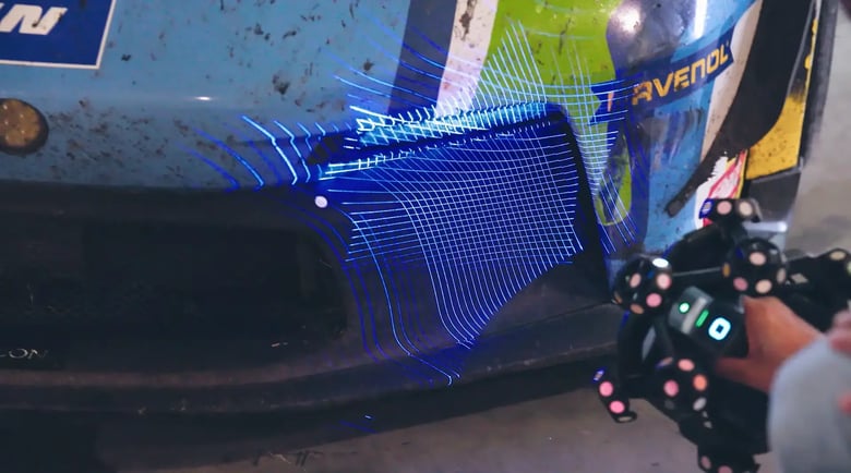
People walking through the scan area, rotating fans, moving machinery, swinging cables, changing reflections, and other motion can introduce unwanted data or confuse tracking.
This is particularly important when scanning large objects in workshops, production areas, garages, or outdoor environments.
Keep the immediate scan area as still as practical.
If someone needs to walk through the workspace, pause scanning until the area is clear.
Adjust Brightness Before the Data Gets Noisy
Exposure or brightness settings should be adjusted based on the surface being scanned.
If the setting is too low, dark areas may appear incomplete.
If it is too high, bright or reflective surfaces may produce excessive noise.
Instead of relying on one setting for the entire object, use the live preview to determine whether the scanner is collecting consistent data.
On objects with mixed materials, you may need to adjust brightness as you move from one section to another.
For example, a black plastic housing may require different settings than a nearby polished metal bracket.
The goal is not to make the live image look bright. It is to produce clean, stable scan data with as little noise as possible.
Reduce Strong Reflections
Reflections can introduce false or unstable points.
Highly polished metal, glossy paint, chrome, glass, and other reflective materials may redirect the scanner's projected light away from the cameras or create confusing reflections.
Changing the scanning angle can often help.
Instead of looking directly at the reflective surface, approach it slightly off-axis and watch the live data.
Diffuse lighting can also help reduce harsh environmental reflections.
If the material remains difficult, temporary scanning spray may be the most effective solution.
It is usually better to solve the reflection problem during scanning than to spend significant time deleting noisy points afterward.
Capture Difficult Features Deliberately
Holes, pockets, undercuts, narrow edges, and internal corners often need more attention than the rest of the object.
Do not assume they will fill in automatically while you scan the surrounding surface.
After capturing the main body of the object, return to these features and inspect them individually.
Change the viewing angle, use a more focused scan mode if available, and make sure the data is actually being collected.
For deep or obstructed geometry, repositioning the part may provide a much better result than repeatedly scanning from a poor angle.
The goal is to capture real measured geometry wherever possible instead of relying on mesh repair later.
Scan Enough Overlap Between Sections
When scanning around a large object, each new area should share enough geometry with the previous section to maintain reliable alignment.
If you move too far into completely new geometry, the scanner may lose its reference.
On the other hand, staying almost entirely within areas that have already been captured wastes time and creates unnecessary duplicate data.
A good rhythm is to keep part of the existing scan visible while gradually moving into new territory.
This gives the software enough information to maintain tracking while continuously expanding the model.
Consider Multiple Scan Projects
Sometimes one enormous scan is not the cleanest workflow.
If the object needs to be flipped, moved, scanned from several orientations, or captured using significantly different modes, splitting the job into multiple projects can make the data easier to manage.
Each project can be captured and cleaned independently before alignment.
This is particularly useful for objects that have hidden surfaces underneath them.
Instead of repositioning the part halfway through an active scan and risking alignment problems, complete the first orientation, create another scan for the second orientation, and merge the projects afterward.
Just make sure the projects contain enough shared geometry or marker information to align reliably.
Remove Obvious Background Data Before Meshing
Once the scan is complete, do not immediately generate the mesh.
First review the point cloud or raw scan data.
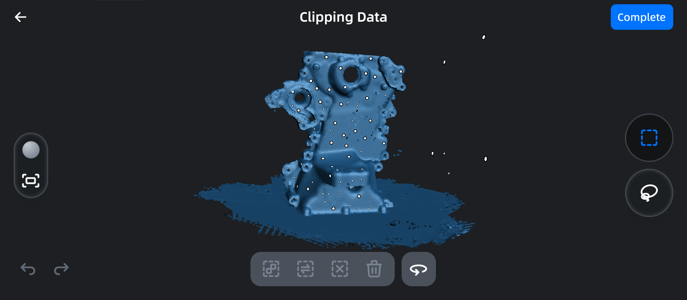
Remove obvious background surfaces, stray points, turntable geometry, fixtures, and other information that is not part of the object.
Cleaning at this stage gives the meshing algorithm a much clearer data set to work with.
For example, if a mechanical part was scanned while sitting on a table, remove the table before generating the final mesh.
Otherwise, the software may attempt to connect the part and table or create unnecessary surfaces between them.

Look for Floating Noise
Small clusters of points may occasionally appear around the object without being connected to the real surface.
These can come from reflections, environmental movement, exposure issues, or temporary tracking problems.
Before meshing, rotate the scan and look for floating data around the model.
Delete anything that clearly does not belong.
Pay particular attention around reflective surfaces and edges, where false points can sometimes appear farther away from the actual geometry.
Cleaning these areas beforehand helps prevent strange triangles and surface artifacts in the finished mesh.
Check for Double Surfaces
Double surfaces are often a sign of alignment or movement problems.
You may notice two slightly offset versions of the same edge or surface.
If that happens, do not assume meshing will fix it.
Go back and determine where the duplicate geometry came from.
It may be caused by a tracking error, the object moving during capture, or two scan projects being aligned incorrectly.
Correcting the underlying alignment before meshing produces a much better result than trying to smooth the problem away later.
Inspect Thin and Detailed Areas
Thin walls, sharp edges, small tabs, fins, and narrow features deserve a close look before processing.
These areas can appear complete from one viewing angle while actually containing gaps or inconsistent data on the opposite side.
Rotate the scan and inspect them from several directions.
If a thin feature matters to the final model, it is better to add a little more scan data now than discover after meshing that the software has merged two surfaces together or filled the area incorrectly.
Check the Entire Model for Missing Areas
Before meshing, rotate the scan through a full 360 degrees.
Look underneath the object, along the back side, around recessed features, and anywhere that may have been difficult to reach during capture.
Small missing areas are easy to overlook when you are focused on one side of the object.
If the project is still open for scanning, this is the best time to fix them.
A few seconds of additional scanning can prevent a much larger repair job later.
Do Not Depend on Hole Filling Too Early
Mesh software can often fill missing areas automatically, but that does not mean those surfaces were measured.
For decorative models, visualization, or some 3D printing applications, automatic repair may be completely acceptable.
For reverse engineering or dimensional inspection, missing geometry should be treated differently.
If a surface is important, capture it whenever possible.
A mathematically smooth filled surface may look excellent while being completely different from the physical part.
Clean scan data gives you the option to decide how the geometry should be handled rather than allowing the meshing algorithm to make that decision for you.
Choose an Appropriate Point Distance
Very dense scan settings can capture excellent detail, but they also create larger projects and longer processing times.
Not every object needs the smallest possible point distance.
A large vehicle panel does not normally require the same point density as a small machined component with fine features.
Choose a resolution appropriate for the smallest geometry you actually need to preserve.
If the scanner allows different resolutions within the same project, use finer settings selectively.
This can keep the overall data set manageable while preserving important detail where necessary.
Keep the Final Application in Mind
The definition of "clean" data depends partly on what you plan to do with it.
For 3D printing, the priority may be creating a visually complete and watertight model.
For reverse engineering, clear edges, holes, profiles, and mechanical features may matter more than having every cosmetic surface perfectly filled.
For inspection, preserving measured geometry and avoiding artificial smoothing or reconstruction is especially important.
For visualization, surface appearance and texture may take priority over dimensional fidelity.
Knowing the final goal helps you decide which imperfections need to be corrected during scanning and which can safely be handled later.
Example: Mechanical Part for Reverse Engineering
Imagine scanning an aluminum housing that will eventually be recreated in CAD.
Start by securing the part and capturing its major surfaces with stable tracking.
Rather than repeatedly scanning the same faces, concentrate on getting clean coverage of the edges, bolt holes, mounting features, ribs, and other geometry that will define the CAD model.
If reflective areas produce noise, change the scanning angle or apply appropriate surface preparation.
Before meshing, remove the table and any floating points, then inspect the holes and important edges for missing data.
The resulting mesh may not need to look perfectly polished.
What matters is that the geometry used to reconstruct the part is clean, consistent, and based on reliable measurements.
Example: Automotive Body Panel
A body panel presents a very different scanning problem.
The surface may be large, smooth, reflective, and relatively featureless.
In this case, tracking stability and surface consistency become the priorities.
Markers may provide a much stronger reference than natural geometry, while an appropriate laser mode can reduce problems from dark or glossy paint.
Move smoothly across the panel with controlled overlap rather than repeatedly sweeping the same region.
Once the scan is complete, inspect the edges and mounting features carefully and remove any floor, stand, or surrounding vehicle geometry before meshing.
A clean point cloud will give the meshing software a much better chance of reproducing the smooth panel without unnecessary surface artifacts.
Example: Object for 3D Printing
For an object intended for 3D printing, the requirements may be more forgiving.
The scan still needs good coverage and stable tracking, but small missing areas can often be repaired later.
The priority is capturing enough real geometry that the software can reconstruct the object without making large assumptions.
Before meshing, remove background data and obvious noise, confirm that major surfaces are present, and make sure thin or detailed features have enough information to survive processing.
Once the raw data is clean, watertight meshing and additional repair tools can be used to prepare the model for printing.
Clean Data Saves Time Later
The best time to fix a scanning problem is usually while you are still scanning.
It is far easier to change your angle, capture another pass, adjust brightness, add markers, or reposition the object than it is to reconstruct missing geometry after the scan is finished.
Before generating a mesh, take a few minutes to rotate the raw scan and look for problems.
Check tracking alignment, missing surfaces, duplicate geometry, floating points, unnecessary background data, and areas where the point cloud suddenly becomes noisy.
If something does not look right, determine whether it can be corrected with cleanup or whether the area should be rescanned.
Conclusion
Cleaner 3D scan data is not primarily the result of aggressive software cleanup.
It comes from controlling the scanning process from the beginning.
Stable positioning, reliable tracking, appropriate scan settings, consistent working distance, controlled movement, good surface preparation, and deliberate coverage all contribute to a cleaner point cloud.
Once scanning is complete, removing unnecessary background data and checking the model carefully before meshing gives the processing software a much better starting point.
The result is faster meshing, fewer artifacts, less manual repair, and a final model that more accurately represents the object you actually scanned.