

How to 3D Scan Symmetrical and Repetitive Objects
10th Sep 2026
Symmetrical and repetitive objects can be surprisingly difficult to 3D scan.
At first glance, they may look simple. A smooth wheel, a cylindrical part, a repeated row of fins, or a panel with identical holes does not seem especially complicated.
But from the scanner’s point of view, the problem is not complexity. It is uniqueness.
3D scanners need enough recognizable information to understand where they are relative to the object. When several areas look nearly identical, the software can struggle to tell one section from another. That can lead to tracking loss, incorrect relocalization, duplicated geometry, or sections of the scan being placed in the wrong position.
SHINING 3D specifically identifies objects with limited features or a high degree of feature repetition as cases that may require additional preparation before scanning.
The solution is usually to give the scanner more unique reference information and plan the scan so it always has something reliable to follow.
Why Symmetry Causes Tracking Problems
Markerless 3D scanning works by recognizing geometry, texture, or a combination of both.
If one side of an object contains a unique hole, edge, logo, curve, or surface transition, the scanner has useful information that helps it determine its position.
Symmetrical objects remove much of that information.
Imagine scanning a perfectly round cylinder. As you move around it, one section of the surface may look almost identical to another.
A wheel with evenly spaced spokes creates a similar problem. Each spoke may look nearly identical to the next.
The scanner may know what shape it is looking at, but it can have difficulty determining exactly where on that shape it is currently positioned.
Repetitive industrial geometry can create the same issue. Cooling fins, identical bolt holes, repeating ribs, perforated panels, and patterned structures may all give the scanner many visually similar references.
Start on the Most Unique Area
When possible, begin the scan on the most recognizable part of the object.
Look for asymmetrical geometry such as a mounting bracket, irregular opening, embossed text, logo, unique edge, damaged area, connector, or other feature that appears only once.
Capture that area first and allow the scanner to establish a strong reference before moving toward the more repetitive sections.
This is usually much more reliable than starting in the middle of a smooth or highly repetitive surface.
Once the software has a stable reference, move gradually into neighboring geometry while keeping some of the already captured area visible.
Keep Unique Geometry in View
As you move across a repetitive object, try not to leave all recognizable geometry behind at once.
If you are scanning a cylindrical housing with one unique mounting flange, for example, keep part of that flange visible as you begin moving around the cylinder.
Gradually expand the scan rather than jumping immediately to the opposite side.
This gives the software overlapping information between the unique area and the repetitive area.
The same idea applies to wheels, gears, fans, turbine components, repeated fins, and other rotationally symmetrical parts.
Think of the scan as a chain of connected references.
Each new section should contain enough information from the previous section that the software can confidently determine where it belongs.

Use Reflective Markers When Geometry Is Not Enough
Reflective markers are one of the most reliable solutions for symmetrical and repetitive objects.
Instead of relying entirely on the shape of the part, the scanner can track the unique arrangement of markers across the surface.
SHINING 3D specifically recommends marker alignment for objects that lack sufficient surface features or contain repetitive features.
The important part is how those markers are placed.
Markers should be distributed evenly but randomly. Avoid straight lines, obvious grids, equal spacing, or repeated patterns.
If the markers themselves form a symmetrical pattern, you have simply created another version of the original problem.
SHINING 3D’s preparation guides repeatedly warn against placing markers in straight lines or artificial groups and recommend scattered, irregular placement instead.

Make the Marker Pattern Unique
A good marker layout should look different from every viewing angle.
For example, instead of placing one marker beside every bolt hole, vary their positions.
Place some slightly higher, some lower, some closer together, and some farther apart.
The scanner is not simply recognizing individual dots. It is using their relative arrangement to understand position.
A random marker pattern creates something much closer to a fingerprint.
As you move around the part, several markers should remain visible at once so the scanner can maintain that reference.
SHINING 3D documentation commonly recommends having at least four markers visible within the working area for marker-based alignment, although the exact requirement can vary by system and settings.
Avoid Perfectly Repetitive Marker Placement
One of the easiest mistakes to make is placing markers in a way that mirrors the geometry.
Imagine a wheel with ten identical spokes.
If you place one marker at the same location on every spoke, the scanner still sees ten nearly identical patterns.
Instead, break the symmetry.
Put markers in different locations across different spokes and include additional markers on nearby geometry.
The goal is to create a positional reference that cannot easily be confused with another section of the object.
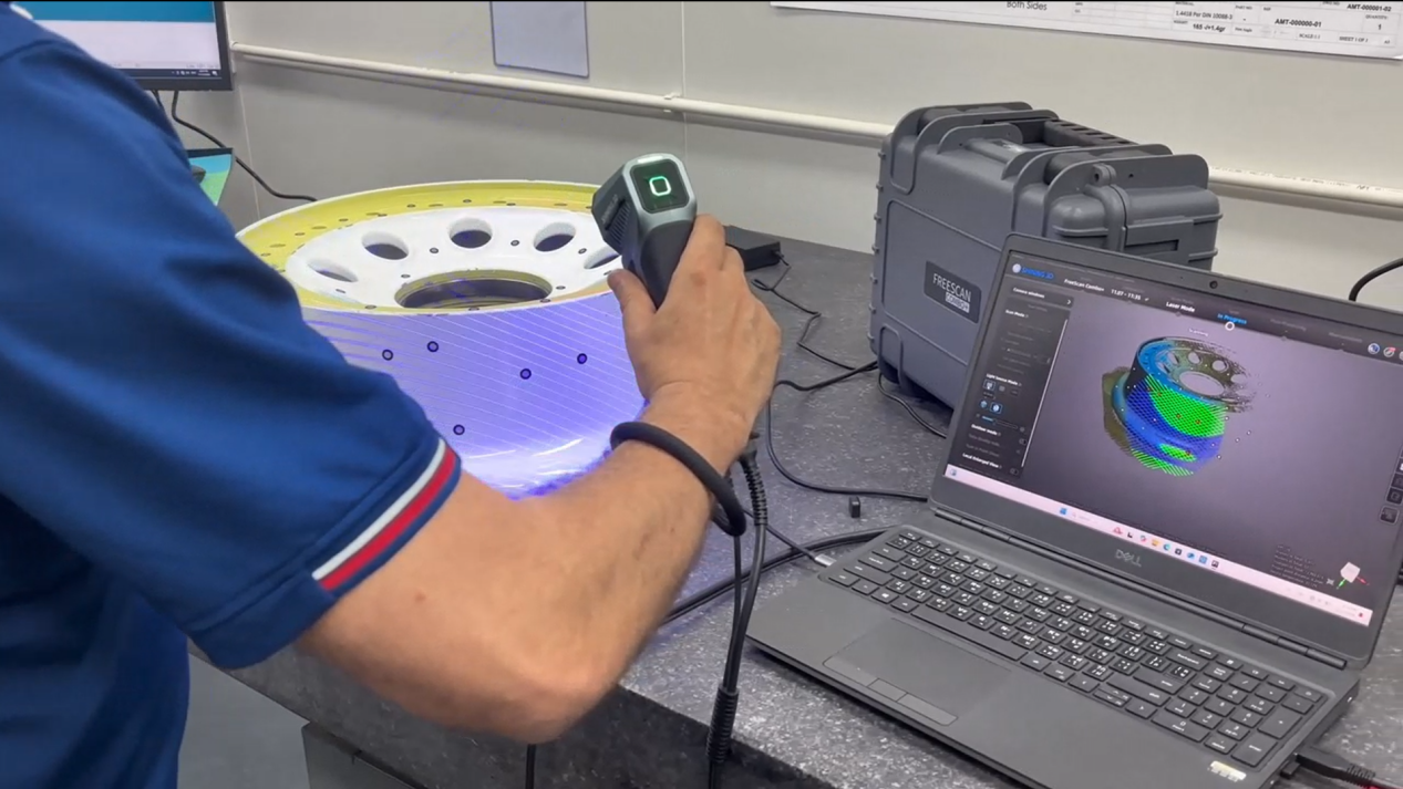
Add Temporary Features for Markerless Scanning
Markers are not always the only option.
If you want to stay markerless, adding temporary unique features can help the scanner distinguish one region from another.
SHINING 3D’s current guidance for objects with limited or repetitive features includes adding random geometric features around the object for feature alignment, or adding temporary visible surface features for texture-based alignment on supported systems.
Depending on the object and the required workflow, that could mean placing small removable objects nearby, using pieces of tape, attaching temporary geometry, or introducing another harmless visual reference.
The important thing is that the added features should be irregular.
A repeating pattern will not solve a repetition problem.
Use Texture When It Is Available
Some symmetrical objects have simple geometry but rich visual texture.
A patterned ceramic vase may be rotationally symmetrical in shape but contain unique artwork or color variations around its surface.
In that situation, texture alignment can provide useful tracking information even when the geometry itself is repetitive.
Likewise, printed labels, scratches, color changes, graphics, or surface markings can sometimes provide enough uniqueness for markerless tracking.
If the object is both geometrically symmetrical and visually uniform, however, texture alignment will have very little to work with.
That is when markers or temporary features become much more useful.
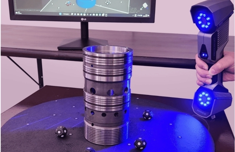
Smooth Cylinders Are a Common Problem
A plain cylinder is one of the simplest examples of a difficult markerless object.
There may be almost nothing telling the scanner whether it has moved five degrees or fifty degrees around the circumference.
If the cylinder has a flange, keyway, label, seam, hole, or fitting, begin there.
Use that feature as the anchor for the scan.
If the cylinder is almost completely uniform, marker tracking is usually a more reliable solution.
Place markers around the circumference in an irregular pattern and make sure enough remain visible as you rotate around the object.
For a movable part, placing markers on a surrounding fixture or scanning surface may also help depending on the scanner and alignment mode.
Wheels, Fans, and Rotational Symmetry
Wheels, fans, rotors, and similar components combine repetition with rotational symmetry.
A wheel may contain five, six, or more nearly identical spokes arranged around a center.
If the scanner loses tracking on one spoke and relocalizes onto another, the data may appear to fit even though it is in the wrong rotational position.
This type of error can be difficult to notice immediately.
A strong marker pattern is especially valuable here.
Place markers irregularly across the wheel and avoid repeating the same arrangement on each spoke.
Also begin around any unique geometry such as a valve stem, logo, damaged region, mounting feature, or asymmetric spoke detail.
That gives the scanner both geometric and marker-based references to work with.
Repeated Holes and Perforated Panels
Rows of identical holes can create another tracking challenge.
A perforated sheet or industrial panel may contain dozens of features, but if every feature is identical and evenly spaced, the scanner still has very little unique information.
This is a good example of why simply having “lots of geometry” does not necessarily mean an object is easy to track.
What matters is whether that geometry is distinguishable.
For a repeated-hole pattern, use markers placed irregularly around the panel or include unique perimeter geometry in the scan.
Try to keep one edge, corner, mounting feature, or other recognizable reference visible as you move across the repeated section.
Repeated Fins and Ribs
Cooling fins, heat sinks, turbine structures, and repeated ribs can be similarly difficult.
The scanner may see a large amount of geometric detail, but neighboring features can look almost identical.
Instead of scanning directly along the repeating pattern for a long distance, approach it diagonally when possible.
This lets the scanner see the repeated features along with surrounding geometry that may be more unique.
Markers can also make a significant difference, particularly on industrial parts where dimensional accuracy is important.
Move Gradually
Fast movement becomes especially risky when the scanner is already working with ambiguous geometry.
Move smoothly and allow plenty of overlap between neighboring areas.
If you jump from one side of a symmetrical object to another, the software may attempt to relocalize using geometry that looks similar but is not actually the same region.
Gradual movement reduces that risk.
Watch the live preview while scanning.
If the geometry suddenly shifts, doubles, twists, or appears to jump into a different position, stop and correct the tracking problem rather than continuing to build more data on top of it.
Do Not Trust a Relocalization Just Because It Looks Close
Symmetrical geometry can make incorrect relocalization look surprisingly convincing.
Suppose the scanner loses tracking on a six-spoke wheel.
When it recovers, it may accidentally align with the neighboring spoke.
Because the geometry is almost identical, the scan can appear normal at first.
But the entire new section is now offset by one spoke.
This is one reason to periodically rotate and inspect the live model rather than concentrating only on the area currently being scanned.
Look at the overall geometry and make sure major features remain where they should be.
Return to a Known Area After Tracking Loss
If tracking is lost, move back to a section that contains strong, unique information.
Do not wave the scanner around the repetitive area hoping it will eventually recognize the correct position.
Return to the original mounting feature, unique edge, marker cluster, or other known section.
Once tracking has recovered correctly, approach the difficult area again gradually.
This is usually much faster than trying to repair a large section of incorrectly aligned data later.
Scan Direction Can Matter
Your path around the object can make tracking easier or harder.
Suppose one side of the part contains unique geometry while the opposite side is nearly featureless.
Start on the unique side and work outward.
Avoid beginning on the featureless side and hoping to reach better geometry later.
For long repetitive objects, it can also help to scan in a path that repeatedly crosses unique references rather than following the repeated pattern continuously.
For example, when scanning a long ribbed component, moving diagonally across the ribs may provide more positional variation than moving directly along them.
Repositioning the Object
If the object needs to be flipped or repositioned, symmetry can make project alignment more difficult as well.
Two separate scans of a symmetrical object may have several possible alignments that appear geometrically valid.
Include unique shared geometry between the scan projects whenever possible.
If there is not enough natural uniqueness, markers can provide a much more reliable common reference.
Do not rely entirely on a smooth cylindrical surface or repeating pattern for multi-project alignment.
The more distinctive the overlap between scans, the easier it will be to determine the correct position.
Turntables Can Help, but They Do Not Remove Symmetry
Turntables are useful because they create controlled movement and allow the scanner to view the object from multiple angles.
But a turntable does not automatically solve a tracking problem caused by symmetry.
If the object is a smooth featureless cylinder, rotating it still presents the scanner with nearly identical geometry.
Depending on the scanner and scanning mode, markers on the object, turntable, or surrounding reference surface may still be necessary.
The key is giving the software a reference that changes uniquely as the object rotates.
Symmetry Matters in Alignment After Scanning Too
The same challenge can appear later when aligning separate scan projects.
If you have two scans of a symmetrical object, automatic feature alignment may find several positions that appear mathematically similar.
Always inspect the result.
Check unique edges, mounting features, marker positions, seams, or other known references before accepting the alignment.
If automatic alignment is ambiguous, manual point alignment or marker-based alignment can provide a better starting position.
Example: Scanning a Wheel
A wheel is a classic repetitive scanning challenge.
Its spokes, openings, and rim may repeat around the entire circumference.
Begin near the valve stem, center logo, or another feature that breaks the symmetry.
If marker tracking is available, place markers irregularly around the wheel and avoid putting identical marker layouts on each spoke.
Capture the unique area first, then gradually work around the circumference while keeping previously captured markers or geometry visible.
Periodically inspect the complete model to make sure the scanner has not jumped from one spoke to another.
Example: Cylindrical Industrial Component
Imagine scanning a long machined cylinder with nearly identical geometry along most of its length.
Begin at a flange, connector, keyway, bolt pattern, or other distinctive feature.
If the central section is completely uniform, use markers to maintain positional reference as you move along it.
Avoid placing markers in straight rings around the cylinder.
Instead, stagger their positions longitudinally and circumferentially so the arrangement remains unique.
This gives the scanner far more reliable information than the cylindrical surface alone.
Example: Repetitive Mechanical Assembly
A mechanical assembly may contain repeated brackets, bolts, ribs, or cooling fins.
The safest approach is to identify the unique geometry around the repeated section before scanning.
Capture the surrounding frame, mounting points, housings, or other irregular features first.
Then enter the repetitive area while maintaining overlap with those references.
If the repeating pattern extends too far for reliable markerless tracking, add markers before continuing.
This prevents the scanner from having to guess where one repeated feature belongs relative to another.
When Markers Are the Better Choice
Markerless scanning is convenient, but there is no advantage in forcing a markerless workflow when the object simply does not provide enough unique information.
If tracking repeatedly fails, the object is highly symmetrical, or several areas look essentially identical, reflective markers can save a significant amount of time.
The same applies when accuracy and repeatability are more important than minimizing preparation.
A few minutes spent creating a reliable marker layout can prevent tracking errors that would otherwise require rescanning or extensive cleanup.
A Better Workflow for Repetitive Objects
Before scanning, look at the object and identify what makes one area different from another.
Start with those unique features.
Move gradually into repetitive geometry while keeping useful overlap with the existing scan.
If the object does not contain enough uniqueness, add it artificially using randomly distributed markers or temporary features.
Watch the full scan as it develops, not just the immediate capture area.
If tracking fails, return to a known reference before continuing.
Most importantly, do not judge tracking quality only by whether new points are appearing.
On a symmetrical object, incorrect data can still look convincing.
What matters is whether that data is being placed in the correct position.
Conclusion
Symmetrical and repetitive objects are difficult to scan because the scanner sees too many areas that look alike.
A smooth cylinder may have almost no unique geometry. A wheel may repeat the same spoke several times. A perforated panel may contain hundreds of features while still offering very little positional information.
The solution is to create stronger references.
Start on unique geometry, maintain overlap, move gradually, and use texture information when it provides useful variation.
When natural features are not enough, reflective markers are often the most reliable option. Place them randomly and avoid layouts that repeat the symmetry already present in the object.
Once the scanner has enough unique information to understand where it is, even highly repetitive parts become much easier to capture reliably.