
Composite vs. Complete Scanning: When to Split a 3D Scanning Project into Multiple Scans
3rd Aug 2026
One of the most important decisions in a 3D scanning project happens before the final mesh is created: should the object be captured as one continuous scan, or should it be divided into several smaller scans that are aligned and combined afterward?
A complete scan keeps the entire object inside one continuous scanning project. The operator moves around the subject while the software maintains tracking and gradually builds a single connected model. This is often the simplest and fastest approach, especially when the object is easy to access and has enough geometry, texture, or markers to support reliable alignment.
A composite workflow takes a different approach. Instead of forcing the entire object into one continuous session, the project is divided into multiple scans. Each section can be captured separately, cleaned individually, and then aligned with the others to form the complete model.
Neither method is automatically better. The right choice depends on the object, the scanning environment, the level of detail required, and how the final model will be used.
What Is a Complete Scan?
A complete scan is built during one continuous scanning session. The scanner begins in one area, establishes tracking, and continues around the object while adding new data to the same project.
This workflow is ideal when the scanner can maintain alignment throughout the entire capture. Objects with distinctive geometry, visible texture, or a well-planned marker layout are often good candidates for complete scanning. The operator can move naturally from one surface to the next without stopping to create separate projects.
Complete scanning also reduces the amount of post-processing required. Because all surfaces are already connected within the same scan, there is usually no need to align several independent data sets before meshing.
For smaller objects, accessible mechanical components, sculptures, people, and parts that can be placed on a turntable, a complete scan is often the most efficient choice.
What Is Composite Scanning?
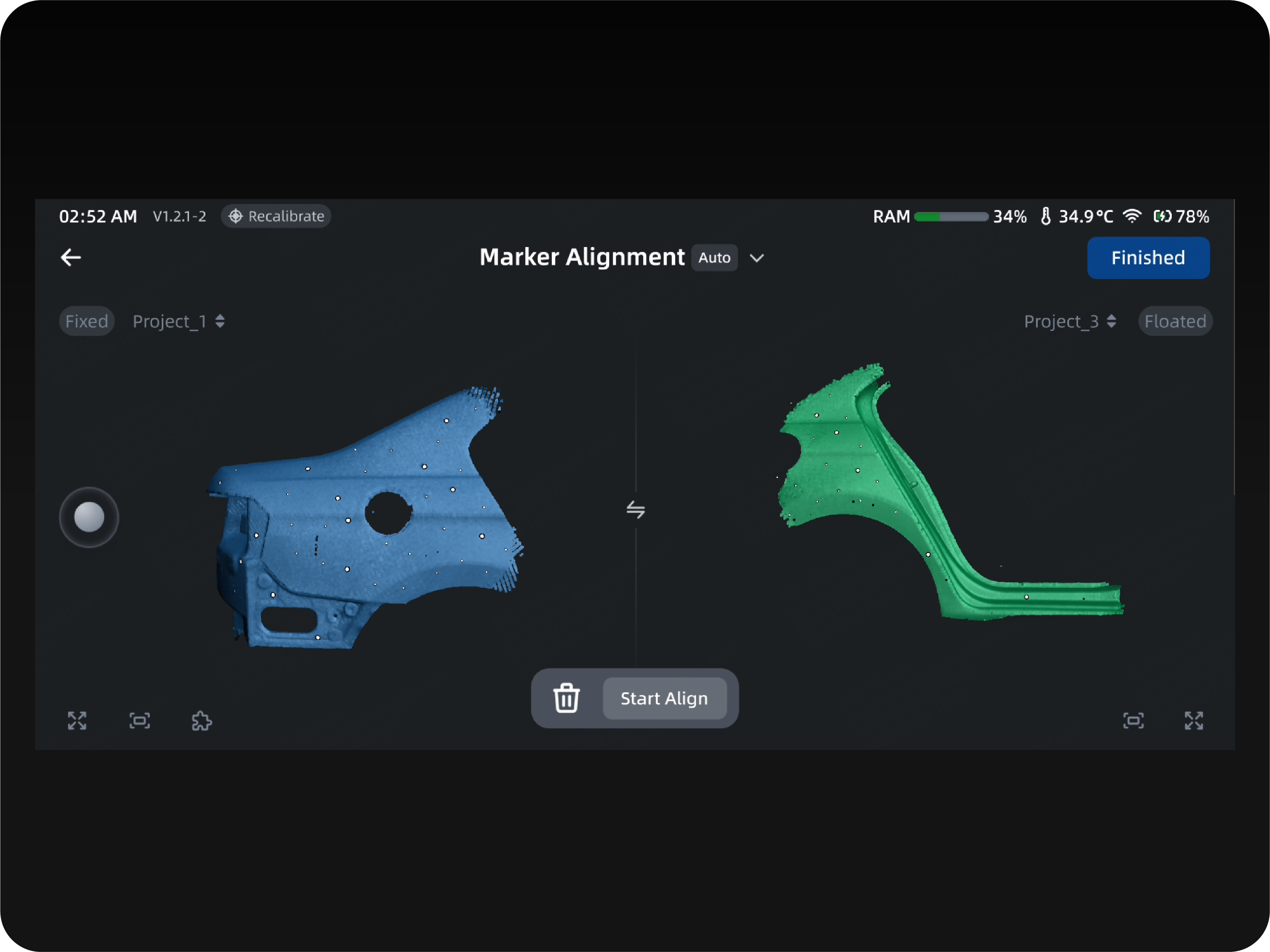
Composite scanning divides the object into multiple individual scan projects. Each scan captures a specific section, angle, orientation, or level of detail. Those scans are then aligned using shared geometry, markers, reference points, or manual alignment tools.
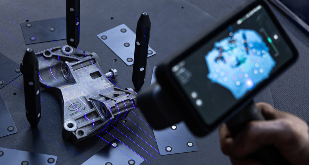
For example, a large automotive component might be divided into a top scan, an underside scan, and several detailed scans around mounting features. A vehicle interior could be separated into the dashboard, center console, driver-side area, and passenger-side area.
The separate scans are cleaned and aligned before the final mesh is generated. This requires additional processing, but it gives the operator greater control over each section of the project.
Composite scanning is especially useful when the entire object cannot be reached from one position, when the object must be moved during capture, or when different sections require different scanning modes.

When a Complete Scan Works Best
A complete scan is usually the best place to start when the object can be captured without repositioning it. If the scanner can move around the subject and maintain tracking across all important surfaces, keeping everything in one project creates a more direct workflow.
This approach works well when the object has enough natural features to help the scanner understand its position. Corners, openings, surface transitions, engraved details, and irregular geometry all provide useful tracking information.
Complete scanning is also practical when reflective markers can remain visible throughout the project. A strong marker layout allows the scanner to move across smooth or repetitive surfaces without losing its reference.
The physical environment matters as well. If there is enough room to walk around the object, reach the necessary angles, and maintain the recommended working distance, there may be little reason to split the project.
The main advantage is simplicity. The operator completes the scan, removes unwanted data, fills minor gaps if needed, and moves directly into meshing or inspection.
When to Split a Project into Multiple Scans
The strongest reason to use a composite workflow is that the entire object cannot be captured reliably as one continuous scan.
This often happens when the object has hidden or obstructed surfaces. The underside of a part, the back of an installed component, or a recessed interior area may be impossible to reach without moving the object or changing the setup.
Once the object is moved, the scanner can no longer rely on the original scene to maintain alignment. A new scan allows the operator to reposition the part, capture the hidden surfaces, and combine them later.
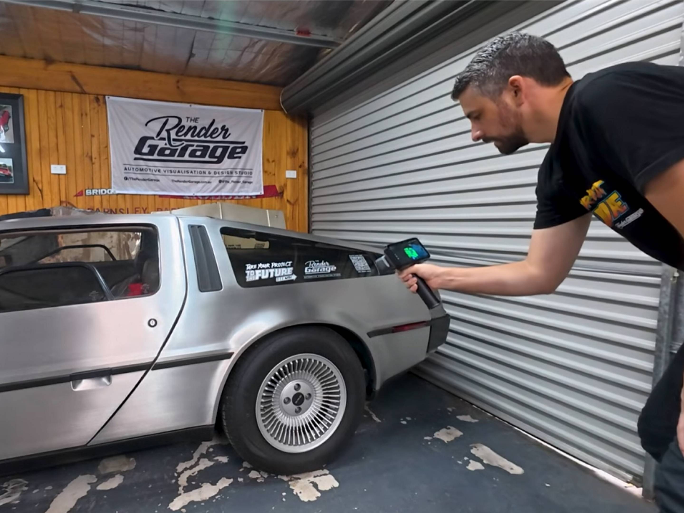
Large objects can also benefit from being divided into manageable sections. A complete vehicle, industrial machine, large mold, or room-sized environment may create an extremely heavy scan project. Breaking the job into sections can make scanning, editing, and processing easier.
A composite workflow can also help when one area repeatedly causes tracking loss. Instead of restarting the entire scan or forcing the scanner through a difficult transition, the problematic area can be captured independently and aligned afterward.
Repositioning the Object
Repositioning is one of the most common reasons to create multiple scans.
A part resting on a table will always have an inaccessible bottom surface. To capture it completely, the object must be turned over or supported in a different orientation. Trying to continue the same scan after moving the part may introduce alignment errors because the surrounding reference points have changed.
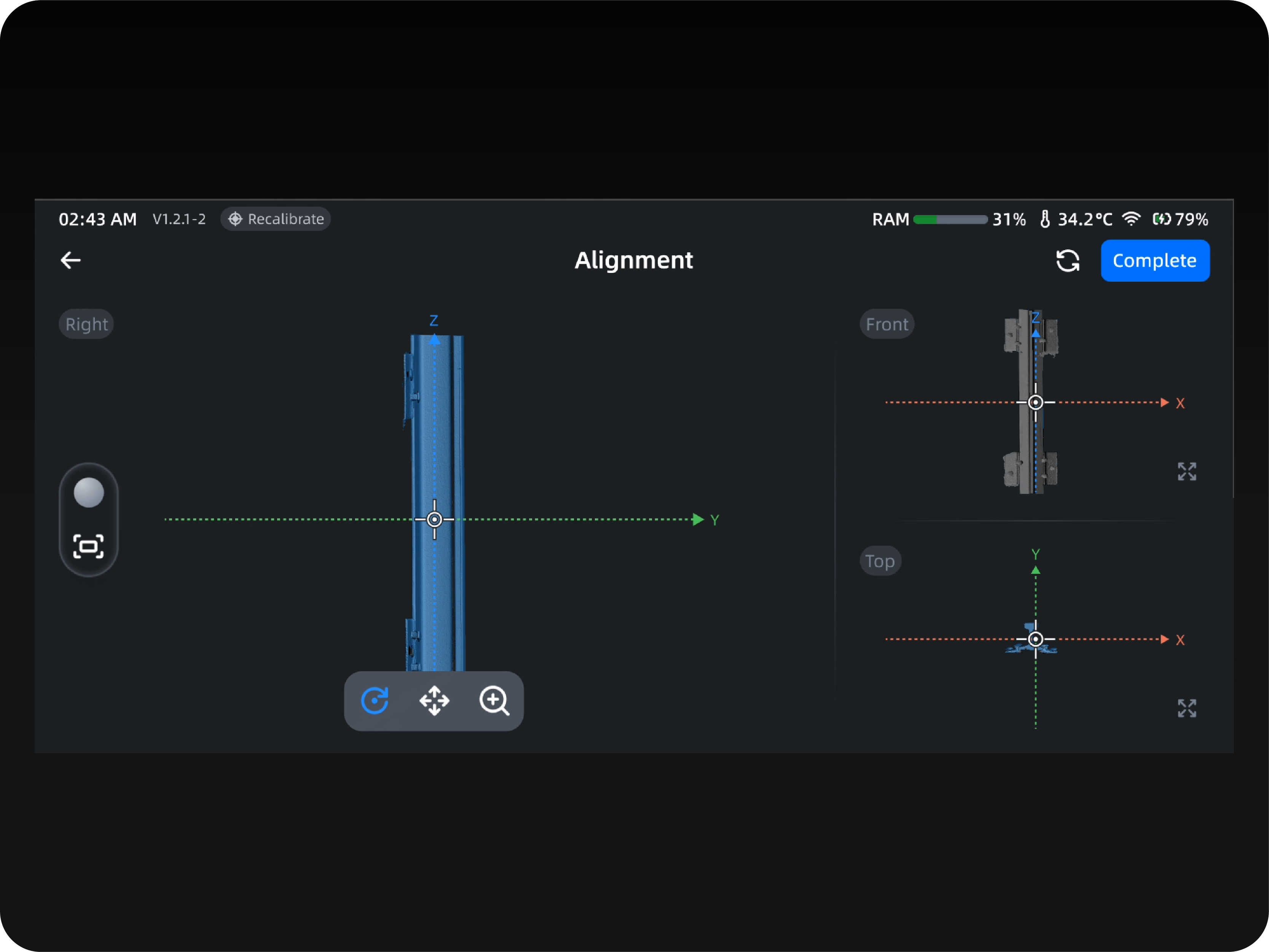
A more reliable approach is to finish the first orientation, save it as its own scan, reposition the object, and begin a second scan. The two data sets can then be aligned using overlapping geometry.
The overlap should include recognizable features rather than only flat or symmetrical surfaces. Holes, corners, ribs, raised details, and irregular contours provide stronger alignment references.
If the two scans share too little unique geometry, reflective markers or temporary reference objects can be used to improve alignment.
Different Scanning Modes for Different Areas
Many modern 3D scanners offer more than one scanning mode. One mode may prioritize fast coverage, while another is optimized for small details or difficult surfaces.
Trying to capture the entire object with a single mode may not always produce the best result.
A large component could be captured quickly with an infrared or high-speed laser mode, while a smaller mounting surface may require a high-detail laser scan. These data sets can be aligned later to create a model that combines efficient broad coverage with detailed local geometry.
This approach is useful when only certain areas require the scanner’s highest resolution. Capturing the entire object at maximum detail can create unnecessarily large data sets and increase processing time.
By splitting the project, each section can be scanned using the settings that make the most sense for that particular surface.
Managing Large Data Sets
A complete scan of a large object can contain millions of points and become increasingly difficult for the computer to process.
As the project grows, the software may become less responsive, especially when high resolution, color texture, and dense point spacing are used. Saving, editing, aligning, and meshing can take longer, and the risk of a software interruption may increase.
Dividing the project into several scans allows each section to remain more manageable. Individual scans can be cleaned before alignment, removing background surfaces and unnecessary data before they are combined.
This reduces the amount of information that the final project must handle. It also makes it easier to repeat a single section if a problem is discovered. Instead of rescanning the entire object, only the affected section needs to be replaced.
Improving Tracking Stability
Long continuous scans can become vulnerable to alignment drift. Small tracking errors may accumulate as the scanner moves farther away from the starting position.
This is more likely on objects with large smooth areas, repeated patterns, or symmetrical shapes. A scanner may appear to track successfully while slowly introducing dimensional error across the project.
Dividing the object into controlled sections can help limit this problem. Each scan begins with a strong local reference and covers a smaller area. The scans can then be aligned using reliable shared geometry or a planned marker system.
For measurement-focused work, this may provide more control than allowing one scan to extend continuously across a very large object.
However, multiple scans do not automatically eliminate alignment error. Poor overlap or weak alignment features can create new problems. Composite scanning works best when the scan divisions are planned before capture begins.
Planning the Overlap
Successful composite scanning depends on overlap. Each neighboring scan needs enough shared information for the software to understand how the sections fit together.
A narrow strip of flat surface is rarely enough. The overlapping area should include several features with depth and variation.
For a mechanical part, useful overlap might include a combination of holes, edges, bosses, ribs, and curved transitions. For an organic object, the overlap may include folds, contours, and visible surface texture.
The operator should usually capture more overlap than seems necessary. Extra shared data can be removed later, but missing alignment information may require the section to be rescanned.
The overlap must also be captured clearly in both scans. If one scan contains clean detailed geometry and the other contains noisy or incomplete data, the software may struggle to align them accurately.
Using Markers in Composite Projects
Reflective markers can make composite scanning significantly easier, particularly on smooth, symmetrical, or featureless parts.
Markers create artificial reference points that the scanner and alignment software can recognize. If the same marker pattern appears in two scans, those scans can often be aligned more reliably than they could be using surface geometry alone.
Marker placement should be random rather than arranged in straight lines or repeating patterns. Each scanning view should contain several markers, and neighboring sections should share enough of the same marker layout to support alignment.
When the object must be repositioned, markers attached directly to the object move with it and remain useful. Markers placed only on the table or surrounding environment will no longer match after the part is moved.
For very large projects, reference targets, marker domes, or fixed tracking objects may help create continuity between sections.
Cleaning Before Alignment
Composite projects are easier to align when each scan is cleaned before the data sets are combined.
Unwanted tables, floors, walls, operators, fixtures, and background objects can interfere with automatic alignment. Removing these surfaces gives the software a clearer understanding of the geometry that belongs to the actual part.
Cleaning also reduces file size and makes manual alignment more manageable. It is easier to select matching features when the scan contains only the important surfaces.
However, operators should avoid deleting useful overlap. A surface that appears unnecessary in one scan may be the strongest reference for aligning it with the next section.
A good approach is to create a backup before major editing. The scan can then be cleaned while preserving the option to restore data if an alignment feature is removed accidentally.
Automatic and Manual Alignment
Many scanning applications include automatic alignment tools that compare the geometry of two scans and attempt to find their matching position.
Automatic alignment works well when the scans contain substantial overlap and distinctive geometry. In simple projects, the software may be able to combine the sections with very little user input.
Manual alignment is useful when automatic alignment selects the wrong position or cannot identify enough shared features. The operator chooses matching points on each scan, giving the software an initial estimate of how the data sets fit together.
These points should be spread across the overlapping area rather than placed close together. Using several clearly identifiable features produces a stronger starting alignment.
After the initial position is established, a global or fine alignment process can refine the relationship between the scans.
Complete Scanning Is Not Always More Accurate
It may seem that keeping everything inside one scan would automatically produce the most accurate result, but this is not always true.
A long scan can suffer from drift, poor transitions, inconsistent resolution, or tracking errors. If the operator continues despite unstable tracking, the final model may contain warped geometry or duplicated surfaces.
A well-planned composite project can produce a cleaner result because each section is captured under controlled conditions. The object can be positioned for better access, the ideal scanning mode can be selected, and difficult areas can receive more attention.
At the same time, unnecessary splitting can create its own alignment challenges. Every additional scan introduces another connection that must be solved accurately.
The goal is not to create as few scans or as many scans as possible. The goal is to use the simplest workflow that produces reliable geometry.
A Practical Decision Process
Before scanning, consider whether the entire object can be reached without moving it. Check whether the scanner can maintain a suitable angle and working distance across all important surfaces.
Look for areas that may cause tracking problems, including large flat panels, repeated geometry, deep openings, and smooth symmetrical shapes.
Consider whether different sections require different scanning modes or resolutions. Also estimate how large the final data set may become and whether the available computer can process it comfortably.
If the object is fully accessible, visually distinctive, and manageable in size, begin with a complete scan.
If the object must be repositioned, contains hidden surfaces, requires several scanning modes, or is likely to create an extremely large project, plan a composite workflow from the beginning.
Example: Scanning an Automotive Component
Consider a large automotive intake assembly with a detailed upper surface, narrow side passages, mounting flanges, and an inaccessible underside.
The main body could be captured as one scan using a fast laser mode. A second scan could focus on the underside after the component is repositioned. Smaller scans could then be used for deep openings or mounting features that require a more focused scanning mode.
Each scan would include overlap around the edges, bolt holes, and structural ribs. These recognizable features would provide strong alignment references.
This approach avoids forcing the scanner to capture every surface from an awkward angle and allows each area to be scanned using the most appropriate settings.
Example: Scanning a Vehicle Interior
A vehicle interior presents a different challenge. The dashboard, seats, center console, floor, door panels, and rear compartment may all be visible from different positions, but maintaining one continuous scan across the entire cabin can be difficult.
The operator may divide the interior into several sections. One scan could capture the dashboard and front console, another could capture the driver’s area, and additional scans could cover the passenger side and rear seating area.
Shared geometry around the console, seat rails, pillars, and door openings could be used to align the sections.
This makes the project easier to manage and allows the scanner to be positioned properly inside the limited cabin space.
When Not to Split the Project
Composite scanning should not be used simply because it is available.
For a small object that can be captured easily on a turntable, dividing the project may add unnecessary work. Each additional scan must be saved, cleaned, aligned, and verified.
Splitting an object with very little recognizable geometry can also make alignment harder. A smooth sphere, plain panel, or repetitive cylindrical part may provide few reliable reference points between scans.
In these situations, a continuous marker-based scan may be more dependable than trying to align several separate sections.
The operator should also consider the final accuracy requirements. For inspection or reverse engineering, every alignment should be checked carefully. A visually convincing composite model may still contain dimensional errors if the scans were aligned poorly.
Final Thoughts
Complete scanning is usually the fastest and simplest choice when the object is accessible, manageable in size, and easy to track. It minimizes alignment work and keeps the entire model inside one continuous project.
Composite scanning becomes valuable when the object must be moved, hidden surfaces need to be captured, different scanning modes are required, or the project becomes too large and complicated for one continuous session.
The most successful composite workflows are planned before scanning begins. Each section should have a clear purpose, sufficient overlap, and reliable alignment features. Scan data should be cleaned carefully, and every alignment should be reviewed before the final mesh is created.
Knowing when to divide a project can save time, reduce tracking problems, and produce better scan data. Instead of forcing every object into the same workflow, operators can choose the approach that best matches the geometry, equipment, and final application.