
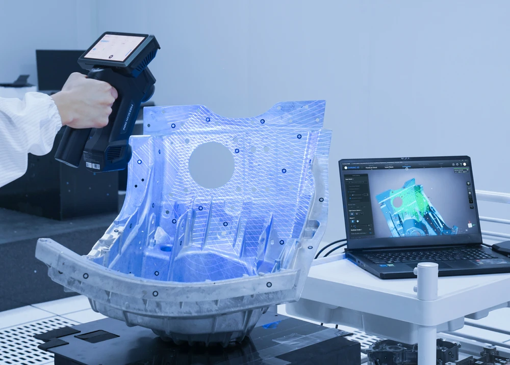
All-in-One Inspection with the FreeScan Omni
11th Aug 2026
Traditional 3D inspection often involves several separate steps. A part is scanned, processed on a workstation, transferred into inspection software, aligned with CAD, analyzed, and finally turned into a report.
The FreeScan Omni is designed to bring those steps together.
By combining metrology-grade 3D scanning, onboard computing, integrated inspection tools, and wireless operation in one handheld system, the Omni allows users to move from physical part to inspection result without constantly returning to a separate workstation.
For manufacturers, quality teams, automotive companies, field-service technicians, and engineering departments, this creates a more mobile and efficient approach to dimensional inspection.
Inspection Directly on the Scanner
The defining feature of the FreeScan Omni is its onboard scan-to-inspect workflow.
Scanning, data processing, inspection, and reporting can all be handled directly on the scanner. Instead of functioning only as a data-capture device, the Omni acts as both the measurement system and the inspection interface.
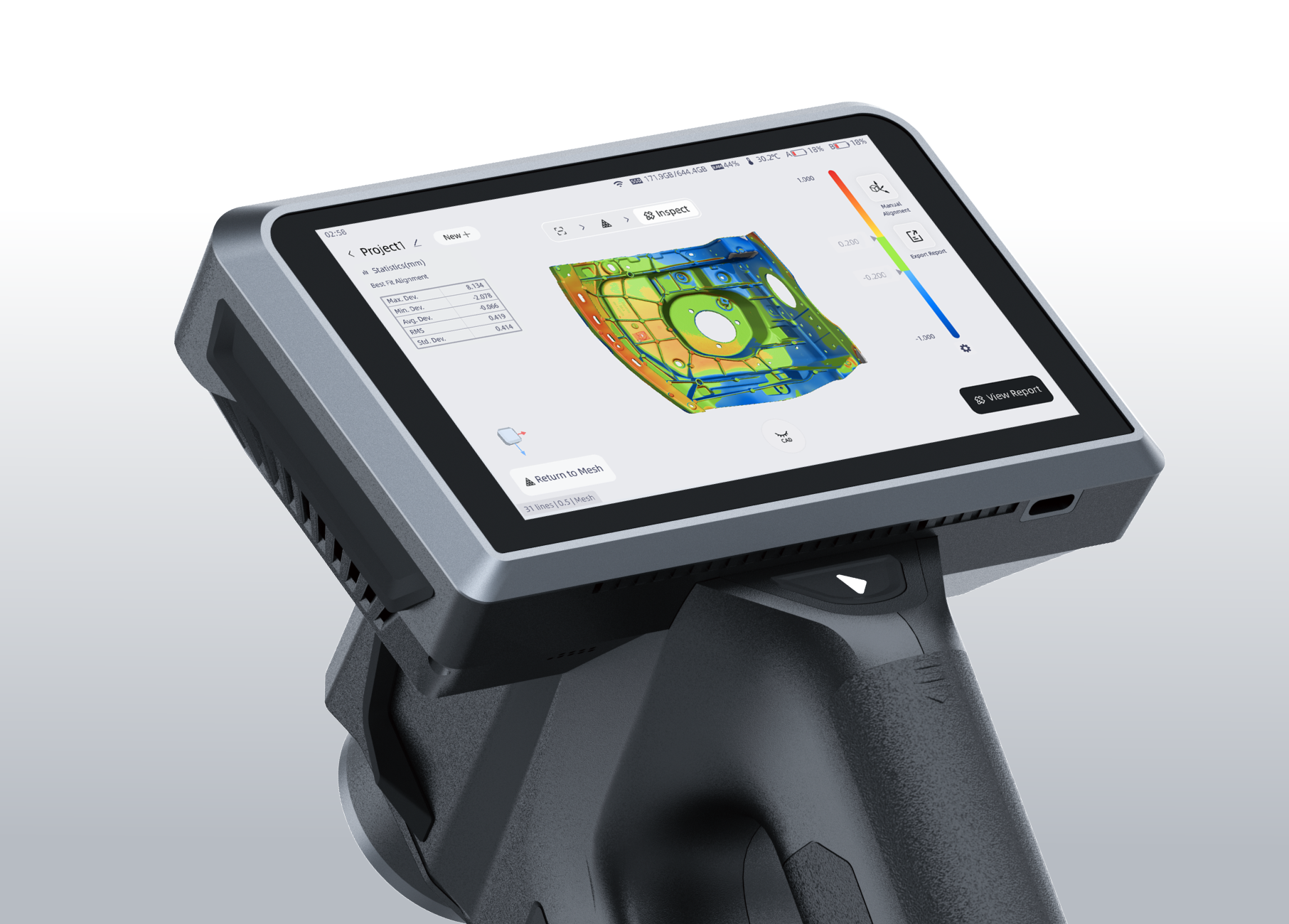
Its integrated SHINING3D Inspect tools allow scanned geometry to be compared against reference CAD directly on the device.
Operators can review deviation maps, inspect geometric features, evaluate dimensional differences, and generate reports while remaining close to the physical part.
This is especially useful on the production floor, where the goal is often to answer a straightforward question as quickly as possible: does this part match the design?
Built for On-Site Quality Control
Many components are inconvenient or impractical to move.
A large casting, battery enclosure, automotive assembly, mold, tooling fixture, or installed machine component may be located far from the inspection lab or simply be too difficult to transport.
The FreeScan Omni brings the measurement system directly to the object.
Its standalone design removes the need for a direct data connection to a separate workstation during scanning, allowing the operator to move freely around the part while reviewing the scan on the integrated display.
This makes the Omni well suited for shop-floor inspection, incoming inspection, first-article inspection, maintenance checks, field measurement, and production troubleshooting.
Metrology-Grade Accuracy
Portability would have limited value if it came at the expense of measurement performance.
The FreeScan Omni provides metrology-grade accuracy up to 0.02 millimeters. Its measurement performance is verified according to VDI/VDE 2634 Part 3 and aligned with ISO 10360 technical standards, with testing performed through SHINING 3D’s ISO/IEC 17025-accredited accuracy laboratory.
For larger components, volumetric performance becomes increasingly important because small tracking errors can accumulate as the measurement area grows.
The Omni supports Video Photogrammetry, or VPG, to help maintain dimensional consistency across larger scan volumes.
Standard volumetric accuracy reaches up to 0.02 + 0.03 millimeters per meter, improving to 0.02 + 0.015 millimeters per meter when VPG is used.
This gives the Omni the flexibility to move between smaller inspection projects and large components without requiring a completely separate photogrammetry system.
Four Scanning Modes for Different Inspection Tasks
Inspection projects rarely contain only one type of geometry.
A single component may include large surfaces, fine mechanical details, deep pockets, reflective areas, and regions where marker preparation is inconvenient.
The FreeScan Omni provides four scanning modes that allow the operator to adapt the workflow to different areas of the same part.
93-Line High-Speed Mode
For capturing the overall component, the Omni uses 93 crossed laser lines and can acquire up to 7,619,000 points per second.
This mode is designed for quickly establishing the overall geometry of the part, making it well suited for castings, automotive panels, fabricated structures, molds, tooling, and other applications where broad surface coverage is the priority.
Once the majority of the geometry has been captured, the operator can switch to more focused scanning modes for areas that require additional detail or access.
25-Line Detail Mode
The detailed scanning mode uses 25 parallel laser lines to capture smaller or more critical geometry.
This can include mounting features, edges, machined areas, surface transitions, and other regions that may play an important role in the inspection result.
Rather than capturing the entire part at the highest available detail, users can scan broad areas quickly and then concentrate higher-density capture where it provides the most value.
Single-Line Deep-Pocket Mode
Deep holes, narrow channels, slots, and recessed features can create line-of-sight problems for wider laser patterns.
The Omni includes a single laser line designed specifically for these difficult areas.
The narrower projection gives the operator greater control when reaching deeper into the geometry and can be useful for castings, machined housings, molds, engine components, turbine parts, and other objects containing recessed features.
IR Rapid Mode
For feature-rich objects where markerless capture is preferred, the Omni also includes an infrared rapid scanning mode.
IR Rapid provides wider, fast surface coverage without requiring reflective markers across the object.
It is useful for preliminary capture, general geometry, and applications where setup speed is more important than achieving the maximum metrology performance available from the blue laser modes.
Handling Difficult Industrial Surfaces
Industrial parts are rarely optimized for optical scanning.
Black plastics, machined aluminum, polished metal, painted components, cast surfaces, and reflective finishes can all present challenges for conventional structured-light systems.
The FreeScan Omni combines blue laser and infrared technologies to give operators more flexibility across these materials.
Its laser modes are especially valuable for dark and reflective industrial components, making the scanner well suited for automotive parts, tooling, castings, machined components, EV battery systems, molds, and heavy industrial equipment.
Some extremely reflective, transparent, or mirror-like materials may still require temporary surface preparation, but the Omni is built around the kinds of real-world materials commonly encountered in manufacturing.
Video Photogrammetry for Large Components
Accuracy across a small component and accuracy across a complete vehicle or large mold are different challenges.
As a handheld scan grows, small alignment errors can accumulate. On larger structures, controlling that cumulative error becomes increasingly important.
The Omni’s Video Photogrammetry workflow helps establish a stronger global reference across the full measurement area.
VPG uses a calibrated scale bar and real-time marker verification to improve volumetric accuracy without requiring a traditional separate photogrammetry camera or coded-marker workflow.
This makes it particularly useful for large automotive components, industrial tooling, molds, structural assemblies, and other projects where overall dimensional consistency matters as much as local surface detail.
AI Feature Recognition
Inspection often depends heavily on geometric features such as holes and slots.
The FreeScan Omni includes AI-assisted feature recognition that can identify boundaries around round holes, rectangular holes, and slots during scanning.
By recognizing these boundaries during capture, the Omni can collect cleaner data around features that may later be used for dimensional inspection.
This can reduce the amount of manual cleanup needed around important mechanical geometry and make the transition from scanning into inspection more efficient.
A Quick FreeScan Omni Inspection Workflow
The advantage of the all-in-one design becomes clearer when looking at a typical inspection project from beginning to end.
Step 1: Prepare the Part and Inspection Template
Before scanning, prepare the component and determine how the finished part will be evaluated.
For a one-off inspection, the Omni can capture the part and perform measurements directly on the device.
For repeatable or automated inspection, a template can first be created in the desktop version of SHINING3D Inspect and then imported onto the Omni.
The template can contain the reference geometry, alignment strategy, inspection features, tolerances, and reporting requirements for the part.
Once imported, the Omni can also bind scanning parameters to the inspection template. These can include scanning mode, point distance, brightness, laser configuration, global marker data, and mesh settings.
This helps standardize not only how the part is inspected, but how the scan data is captured in the first place.
Step 2: Scan the Part
The operator begins by selecting the scanning mode that best suits the geometry.
For a typical industrial component, the 93-line high-speed mode can establish the overall surface quickly.
As the scan develops, the integrated display provides immediate feedback on coverage, tracking, and captured geometry.
Instead of focusing only on making the model visually complete, the operator can prioritize the surfaces and features that will actually be used during inspection.
Mounting faces, holes, edges, transitions, datums, and functional surfaces can receive additional coverage where necessary.
If the component contains deep or narrow features, the operator can switch scanning modes without changing to a different scanner.
Step 3: Review and Process the Scan
Once the important geometry has been captured, the scan can be reviewed directly on the Omni.
Unwanted background data can be removed and the operator can inspect the model for gaps, incomplete regions, or weak coverage.
Because this review happens while the operator is still next to the physical component, missing areas can be corrected immediately.
This avoids the common problem of returning to a workstation only to discover that an important surface was not captured clearly enough.
Step 4: Align the Scan to CAD
The captured model is then aligned with the nominal CAD file.
The correct alignment method depends on the inspection.
A general surface comparison may use a best-fit alignment, while a production inspection may use specific datums, mounting planes, holes, or other functional features.
This distinction is important.
A visually convincing best-fit alignment is not always the correct engineering alignment. When tolerances and functional relationships matter, the scan should be positioned according to the references defined by the inspection plan.
Step 5: Generate the Deviation Map
Once the scan and CAD model are aligned, the Omni can calculate a full-surface deviation map.
The resulting color map provides an immediate visual representation of where the physical component differs from the nominal design.
Areas within tolerance can be distinguished from regions that are too high, too low, warped, or otherwise outside the intended geometry.
A body panel may reveal springback across a broad area. A casting may show gradual deformation. A mold may reveal localized wear.
Instead of evaluating only isolated measurements, the operator can see how the complete visible surface compares with the design.
Step 6: Inspect Critical Features
Full-surface comparison gives the overall picture, but specific dimensional features can also be evaluated.
The operator can inspect holes, distances, surface positions, and other important geometry defined by the inspection plan.
Because the Omni can recognize common hole and slot boundaries during scanning, those areas can be captured more cleanly for later measurement.
For recurring inspections, predefined templates make this stage considerably faster.
The next part can be scanned using the same capture settings, alignment strategy, tolerances, and inspection requirements as the previous one.
Step 7: Generate the Report
Once the inspection is complete, the results can be turned into a report directly on the Omni.
For template-based inspections, the report structure is prepared as part of the SHINING3D Inspect template before it is transferred to the scanner.
Once that workflow is configured, the Omni can populate the report with results from the newly scanned component.
Reports can include deviation maps, dimensional measurements, tolerance results, and other inspection information needed for quality documentation.
This makes recurring inspection particularly efficient: scan the component, run the predefined inspection, review the results, and generate a ready-to-share report without returning to a workstation.

Repeatable Inspection with Templates
The Omni becomes especially valuable when the same component needs to be inspected repeatedly.
Once an inspection template has been created, the workflow can standardize alignment, measurements, tolerances, report content, and many of the scanning parameters used during capture.
This helps reduce variation between operators and minimizes the amount of setup required for every new part.
Instead of rebuilding the inspection from scratch, an operator can select the appropriate template and follow a consistent process from scanning through reporting.
For production environments, this makes full-surface 3D inspection easier to scale across more components and more users.
Why the All-in-One Workflow Matters
The biggest advantage of the FreeScan Omni is not simply that it removes cables.
It reduces the number of transitions between different stages of the inspection process.
In a traditional workflow, the operator may scan the part, return to a computer, process the mesh, discover missing data, return to the part, scan again, transfer the project, perform the inspection, and finally prepare the report.
Every transition adds time and creates another opportunity for incomplete information.
With the Omni, the operator can scan, review, inspect, and verify the result while remaining next to the component.
If something is missing, it can be corrected immediately.
If the part fails inspection, the problem can be identified while manufacturing or engineering personnel are still nearby.
The result is a shorter path between measurement and decision-making.
Standalone When You Need It, PC-Assisted When You Want It
The Omni is designed around standalone inspection, but it is not limited to standalone use.
For larger or more complicated projects, the scanner can also work with FreeScan Omni desktop software.
The PC-assisted workflow provides additional tools for larger data sets, multi-project management, resolution fusion, data editing, and more customized processing.
This gives users the flexibility to keep routine inspection completely portable while still taking advantage of workstation processing when a project demands it.
The Omni does not need to replace every traditional metrology workflow. Instead, it gives teams more flexibility in deciding how much infrastructure a particular inspection actually requires.
Where FreeScan Omni Fits Best
The Omni is especially useful when inspection needs to happen near the part rather than near the inspection equipment.
Automotive teams can inspect body panels, tooling, castings, battery enclosures, structural components, and assemblies directly on the shop floor.
Manufacturers can perform first-article inspection, incoming inspection, production checks, and troubleshooting without constantly transporting parts to a dedicated measurement lab.
Heavy-industry and field-service teams can inspect installed machinery, pipelines, structural components, and equipment that may be impractical to move.
Aerospace maintenance teams can use full-surface measurement to evaluate deformation, damage, and surface variation directly on large structures.
Across these applications, the common advantage is mobility.
The object stays where it is. The inspection system comes to it.

Final Thoughts
The FreeScan Omni represents a different approach to handheld metrology.
Rather than treating scanning, processing, inspection, and reporting as separate operations, it brings them together in one portable workflow.
Its 93-line high-speed laser mode handles broad surface capture, while its detail and single-line modes address more challenging geometry. IR Rapid provides a fast markerless option, Video Photogrammetry supports better large-object volumetric performance, and AI feature recognition helps improve capture around common mechanical features.
But the most important advantage comes after the scan.
With inspection and reporting available directly on the device, the FreeScan Omni allows quality teams to evaluate components where they are manufactured, installed, or maintained.
For companies looking to move inspection closer to production and shorten the path from measurement to decision, the FreeScan Omni provides a complete mobile scan-to-inspect workflow.