
Accuracy and Tolerance: What Do You Actually Need from a 3D Scanner?
3rd Aug 2026
Accuracy is often one of the first specifications people compare when choosing a 3D scanner. A scanner rated at 0.02 millimeters may seem automatically better than one rated at 0.05 or 0.1 millimeters, but the smallest number is not always the most practical choice.
The right level of performance depends on what you are scanning, how the data will be used, and how much dimensional variation the final application can accept.
A scanner used to capture a person for a digital model does not need the same measurement performance as one used to inspect a precision-machined component. A restoration shop recreating an interior trim panel may have different requirements from a manufacturer checking whether a critical feature is within specification.
Before choosing a scanner, it helps to understand four related terms: accuracy, resolution, tolerance, and repeatability.
Accuracy, Resolution, Tolerance, and Repeatability
Accuracy describes how closely a scanner’s measurement matches the true dimensions of the physical object.
If a feature is exactly 100 millimeters long and the scanner measures it as 100.03 millimeters, the result differs from the true value by 0.03 millimeters.
Scanner accuracy is commonly stated as a plus-or-minus value. A scanner rated at an accuracy of 0.05 millimeters is designed to produce measurements within that range under its specified test conditions.
Real-world results can also be affected by calibration, surface material, lighting, scanning distance, tracking quality, object size, temperature, and operator technique.
Resolution describes how closely the scanner can space the individual points it captures. Higher resolution creates a denser point cloud and can reproduce smaller surface features.
Resolution does not automatically determine dimensional accuracy. A scanner may reproduce fine texture while still having a larger overall measurement error. Another system may produce highly accurate measurements without capturing every small scratch or surface imperfection.
Tolerance is the amount of variation allowed in the finished part or assembly. It comes from the design or manufacturing requirement rather than the scanner.
A drawing may specify that a feature should measure 50 millimeters with a tolerance of plus or minus 0.1 millimeters. The part is acceptable as long as that feature falls between 49.9 and 50.1 millimeters.
Repeatability describes whether the same scanning process produces similar results when repeated. This becomes important in inspection and production environments, where users need confidence that another scan or another operator will reach a comparable result.
Matching Scanner Accuracy to Part Tolerance
A scanner should not be selected simply because its stated accuracy matches the part tolerance.
Suppose a feature has a tolerance of plus or minus 0.1 millimeters. A scanner rated at plus or minus 0.1 millimeters would not provide enough separation between the possible measurement error and the allowable part variation.
A component near the acceptance limit could appear either good or bad depending on the scanner’s measurement uncertainty.
A common starting point is to use a measurement system that is approximately four times more accurate than the tolerance being evaluated. Under that guideline, a feature with a tolerance of plus or minus 0.1 millimeters would ideally be measured with a system capable of approximately 0.025-millimeter accuracy or better.
Some industries or internal quality procedures may require a more conservative ratio, while less critical applications may accept a smaller margin. The appropriate relationship depends on the risk, inspection procedure, and measurement requirements.
The important point is that the scanner needs enough accuracy to distinguish actual part variation from measurement uncertainty.
How Accurate Does Your Application Need to Be?
Different scanning applications place very different demands on the equipment.
Visualization, Art, and Digital Archiving
For visualization, character scanning, cultural preservation, artistic work, and virtual content, strict dimensional accuracy may not be the main concern.
Surface detail, color capture, portability, and scanning speed may matter more than whether every measurement is accurate to a few hundredths of a millimeter.
A small dimensional variation may have little practical effect on a digital sculpture, avatar, museum model, or presentation asset.
3D Printing and Custom Fabrication
For 3D printing, the scanner should provide enough accuracy for the printer and the intended fit.
There may be little benefit in producing scan data accurate to 0.01 millimeters if the printer or fabrication process varies by 0.2 millimeters. The complete manufacturing workflow determines how much precision is useful.
Custom automotive panels, enclosures, props, furniture components, and accessories often require reliable overall shape and fit without formal metrology-level inspection.
Critical locations such as mounting holes or mating surfaces can also be verified with calipers, gauges, or physical test fitting.
Reverse Engineering
Reverse engineering can range from approximate shape capture to precision reconstruction of functional parts.
A decorative cover or trim component may allow several tenths of a millimeter of variation. A bracket that must align with existing bolt holes requires more reliable geometry. Bearing surfaces, sealing areas, shafts, bores, and precision assemblies may require substantially tighter control.
The final manufacturing process matters as well. Machining, molding, and precision fabrication can justify more accurate scan data because those processes can reproduce smaller dimensional differences.
It is often useful to identify which features control function and fit before scanning. Broad cosmetic surfaces may not need the same accuracy as mounting points, mating faces, or alignment features.
Inspection and Quality Control
Inspection generally places the greatest demand on scanner accuracy.
The scan must provide enough confidence to determine whether the physical part falls inside or outside its allowed tolerance.
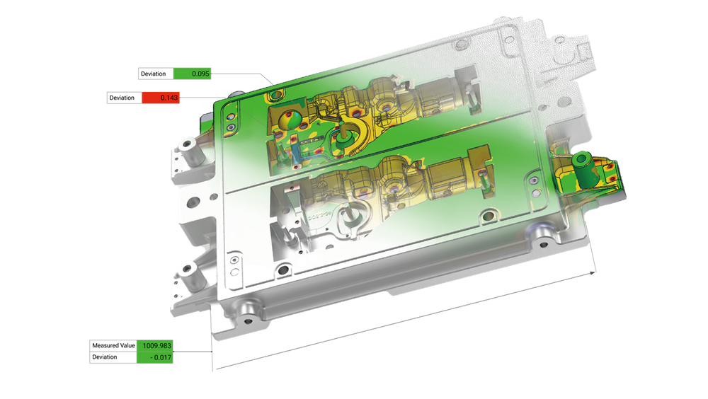
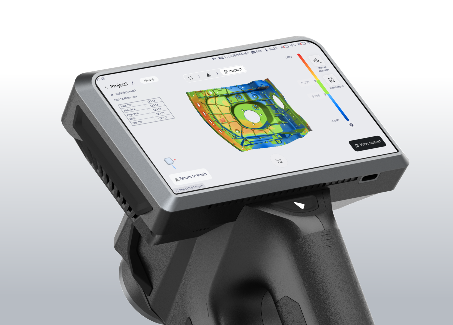
Full-surface scanning can reveal warping, springback, tooling wear, deformation, assembly problems, and manufacturing variation across the complete component. However, the deviation map is only as reliable as the measurement process behind it.
A detailed color map may look precise, but visual detail alone does not prove that the scanner is accurate enough for the tolerance being evaluated.
Formal inspection may require certified accuracy, traceable calibration, repeatability testing, controlled alignment, and dedicated inspection software. In these situations, a metrology-grade scanner is generally more appropriate than a general-purpose system.
Local Accuracy and Volumetric Accuracy
Object size can change how scanner performance should be evaluated.
Local accuracy describes measurement performance within a relatively small area. Volumetric accuracy describes how error may develop across a larger measurement distance.
A scanner may capture a small component accurately but experience more accumulated error across a complete vehicle, mold, aircraft component, or industrial assembly.
Volumetric accuracy is often expressed as a fixed base error plus an additional amount per meter. This specification becomes increasingly important as the object grows.
Large-object systems may use optical tracking, photogrammetry, scale bars, reference targets, or carefully planned marker layouts to control cumulative error.
When evaluating a scanner for large components, the headline local accuracy number should not be the only consideration. It is also important to understand how the system maintains dimensional consistency across the full object.
How the Scanning Workflow Affects Accuracy
The scanner specification is only one part of the measurement process. The way the object is captured, aligned, processed, and inspected can also influence the result.
Tracking and Alignment
Long continuous scans can gradually accumulate drift, particularly across smooth, symmetrical, or repetitive surfaces.
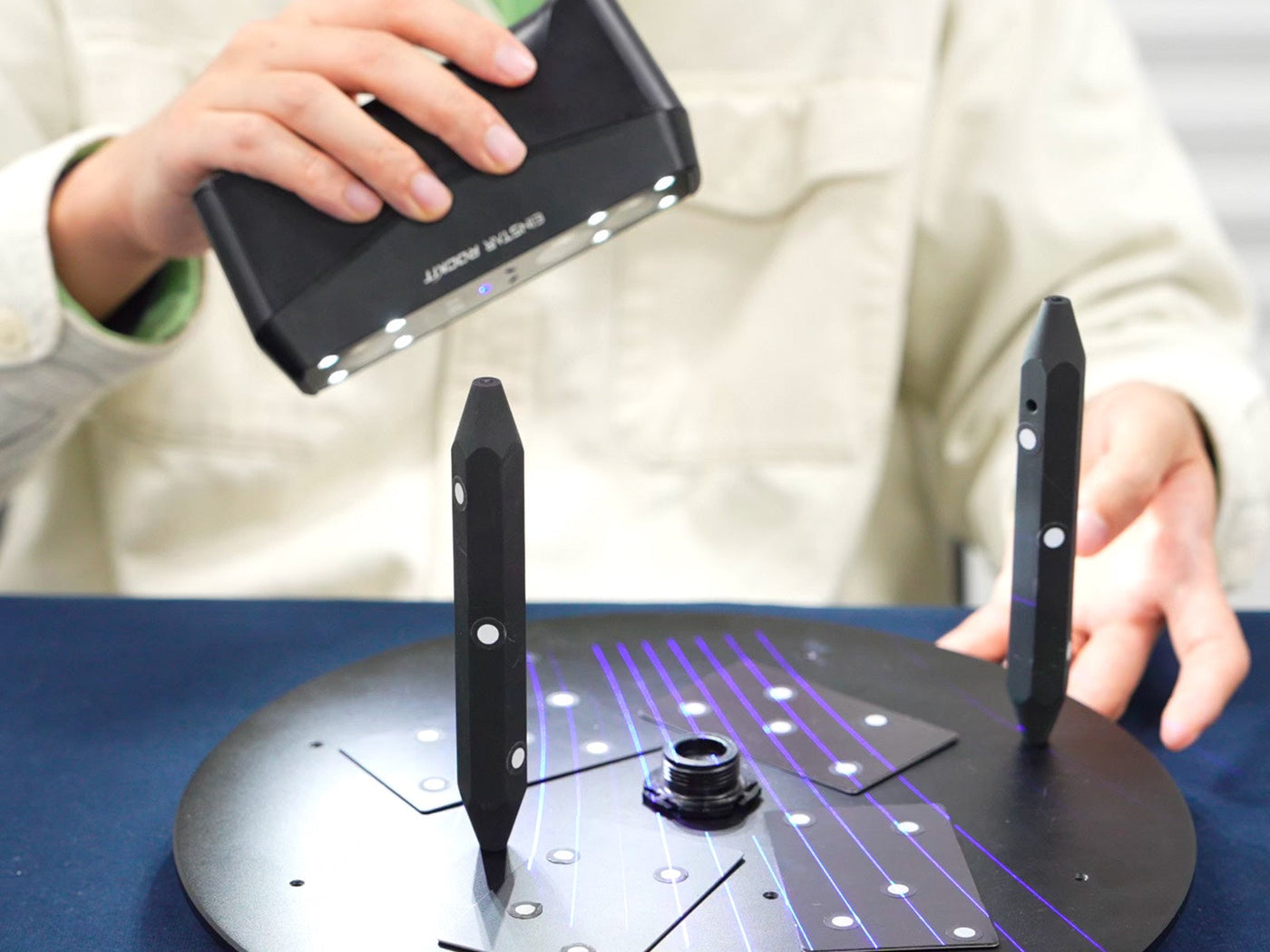
Reflective markers, geometric features, texture tracking, optical tracking, and photogrammetry can help maintain alignment.
Composite workflows, where the object is captured in several separate projects, can improve access and keep data sets manageable. However, each alignment between scans introduces another possible source of error.
For measurement-focused projects, the overlap between scans should contain clear geometry or reliable markers, and each alignment should be checked carefully.
A composite model may appear visually correct while still containing small dimensional shifts between sections.
Surface Preparation
Dark, reflective, transparent, and polished materials can reduce data quality. Scanning spray may improve capture, but the coating adds a small layer to the surface.
For general reverse engineering, that added thickness may be insignificant. For tight-tolerance inspection, the spray application and coating thickness may need to be considered.
The coating should be applied evenly and only as heavily as necessary. Transparent or sublimating sprays may be preferred when cleanup or surface contamination is a concern.
Temperature and Movement
Metal parts expand and contract as temperature changes. A large component measured immediately after machining may not have the same dimensions after reaching room temperature.
Flexible parts, foam, fabric, rubber, upholstery, and people may move by more than the scanner’s stated accuracy during capture.
Vibration, unstable fixtures, loose markers, or object movement can also reduce measurement reliability.
There is little value in selecting an extremely accurate scanner if the object itself cannot remain stable enough to support that level of measurement.
Processing and CAD Reconstruction
Scan data usually passes through several processing stages before it becomes a final mesh, CAD model, or inspection report.
Noise reduction, smoothing, hole filling, mesh repair, alignment, and surface reconstruction can all change the geometry.
Aggressive smoothing may remove legitimate details. Hole filling creates estimated geometry where no scan data was captured. Manual CAD reconstruction can introduce interpretation errors even when the original mesh is accurate.
For inspection, the alignment strategy between the scan and CAD also matters. A best-fit alignment may minimize overall deviation while hiding a functional problem that would be visible using specified datums or mounting features.
Accuracy should therefore be considered across the complete workflow rather than only at the moment of capture.
Repeatability and Verification
A reliable scanning workflow should produce similar results when the same part is measured again.
One practical test is to scan the object several times and compare the results. If the measurements vary significantly between scans, the workflow may not be stable enough for the intended tolerance.
For production inspection, documenting the procedure can improve consistency. This may include the scanner mode, calibration status, marker placement, part orientation, environmental conditions, alignment method, point spacing, and inspection settings.
Critical dimensions can also be checked with a second measurement method such as calipers, micrometers, gauges, a CMM, or another traceable device.
This is especially useful when establishing a new scanning process or verifying that a general-purpose scanner is suitable for a particular reverse engineering application.
General-Purpose Versus Metrology-Grade Scanners
A general-purpose scanner can be the right choice for 3D printing, visualization, education, artistic work, heritage capture, product development, aftermarket fabrication, and moderate-tolerance reverse engineering.
These applications often benefit more from portability, scanning speed, color capture, material adaptability, and ease of use than from certified measurement performance.
A metrology-grade scanner becomes important when the scan will be used to accept or reject parts, inspect tight tolerances, verify tooling, measure deformation, or produce traceable engineering data.
Metrology systems may include certified accuracy, documented calibration, photogrammetry, optical tracking, inspection software integration, and stronger volumetric performance.
The additional capability often comes with greater cost and more demanding workflow requirements. That investment is easier to justify when an incorrect measurement could lead to scrapped components, assembly failure, production delays, tooling changes, or safety concerns.
Higher accuracy is not automatically better for every user. It should provide a practical benefit to the finished project.
Example: Custom Automotive Panel
A fabrication shop may need to scan part of a vehicle interior to design a replacement panel.
The new panel must follow the surrounding contours and align with several mounting locations, but the project may not require a formal inspection report.
A professional general-purpose scanner may provide enough accuracy to capture the overall shape. Critical mounting points can be verified with manual measurements or physical test fitting.
In this situation, portability, reliable surface capture, and convenient tracking may offer more value than a more expensive metrology system.
Example: Inspecting a Machined Housing
A manufacturer may need to inspect a machined housing with tightly controlled mating surfaces, hole positions, and dimensional features.
The allowable variation may be only a few hundredths of a millimeter. A detailed-looking mesh is not enough to determine whether the part passes inspection.
This project calls for a metrology-grade scanner with sufficient accuracy relative to the tolerance, a controlled alignment strategy, repeatable calibration, and dedicated inspection software.
Example: Recreating a Discontinued Component
A maintenance team may need to reproduce a discontinued cast part.
The outer shape and mounting interfaces must be preserved, but some internal geometry may be redesigned for modern manufacturing.
The scan should accurately capture the functional interfaces, while rough cast texture may not require maximum resolution.
The workflow could combine a high-quality scan for the overall form, manual verification of critical features, and CAD reconstruction for the final production model.
This approach focuses measurement effort where it produces the greatest practical benefit.
How to Determine What You Need
Start by identifying how the scan data will be used. Visualization, 3D printing, reverse engineering, and formal inspection each require different levels of measurement confidence.
Determine the tightest tolerance and the smallest important feature in the project. Then consider the accuracy of the final manufacturing process.
A scan does not need to be significantly more accurate than every tool and process that follows it unless the data will be used for formal measurement or future higher-precision work.
Consider the object’s size, material, stability, and accessibility. Large parts may require stronger volumetric accuracy, while reflective or flexible objects may limit the real-world performance of the scanning process.
Finally, determine whether the results must be certified, traceable, or repeatable enough to support production decisions.
These questions provide a much stronger basis for scanner selection than simply choosing the model with the smallest advertised accuracy value.
Final Thoughts
Accuracy is important, but it should always be evaluated in the context of the application.
Resolution determines how much surface detail can be represented. Accuracy describes how closely measurements match the real object. Tolerance defines how much variation the finished part can accept. Repeatability shows whether the process can produce consistent results.
For visualization, education, artistic capture, and many 3D printing projects, a general-purpose scanner may provide everything required. Reverse engineering may combine scan data with manual measurements and functional verification. Formal inspection and tight-tolerance manufacturing generally require a metrology-grade system with traceable performance.
Start with the tolerance, object size, final use, and downstream manufacturing process. Then select a scanner that provides enough measurement confidence without adding unnecessary cost or complexity.