
3D Scanning vs. CMM: Which Measurement Solution Is Right for Your Workflow?
14th Jul 2026
3D Scanning vs. CMM
Manufacturers have more inspection tools available than ever before. Two of the most common solutions for dimensional inspection are 3D scanning and coordinate measuring machines, often called CMMs. Both technologies are used to measure physical parts, verify dimensions, and support quality control, but they work in very different ways.
A CMM is a traditional precision measurement system that collects specific measurement points using a probe. A 3D scanner captures large amounts of surface data quickly, creating a digital representation of the part that can be compared to CAD, inspected, archived, or used for reverse engineering.
Neither technology is simply “better” in every situation. The right choice depends on the part, tolerance requirements, inspection environment, production volume, and what kind of data the user needs. In many modern workflows, 3D scanning and CMM inspection can even complement each other.
What Is a CMM?
A coordinate measuring machine is a precision measurement tool used to inspect the geometry of a physical part. A CMM typically uses a touch probe to contact specific points on the object. Those points are then used to calculate dimensions, positions, shapes, and tolerances.
CMMs are commonly used in manufacturing environments where high precision and repeatable point-based measurement are required. They are especially valuable for inspecting critical dimensions, machined features, holes, planes, slots, datums, and tight-tolerance parts.
Because CMMs are known for accuracy and repeatability, they remain a trusted tool in many quality control departments. For highly controlled inspection of specific features, a CMM is often an excellent choice.

What Is 3D Scanning?
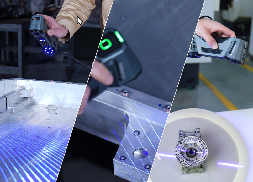
3D scanning captures the shape of an object by collecting dense surface data across the part. Instead of measuring only individual points, a 3D scanner can capture thousands or millions of points across a surface in a short amount of time.
This data can be turned into a point cloud or mesh and then used for CAD comparison, deviation analysis, inspection reporting, reverse engineering, 3D printing, or digital archiving. In inspection workflows, scan data is often compared against a CAD model to show where the physical part differs from the intended design.
3D scanning is especially useful when the part has complex surfaces, organic shapes, castings, molded geometry, large surfaces, or areas that would take a long time to inspect point by point.
The Biggest Difference: Points vs. Surfaces
The simplest way to understand the difference is this: a CMM measures selected points, while a 3D scanner captures entire surfaces.
A CMM is excellent when the user knows exactly which features need to be measured. If the inspection plan calls for specific hole positions, diameters, distances, flatness checks, or datum-based measurements, a CMM can provide highly controlled results.
A 3D scanner is stronger when the user needs to understand the full shape of the part. Instead of only checking a few selected features, scan data can reveal surface deformation, warping, shrinkage, wear, tooling issues, or unexpected variation across the entire object.
This difference is why 3D scanning is often described as full-field measurement. It gives users a broader view of part quality, while CMM inspection provides precise measurement of targeted features.
Speed and Coverage
One of the biggest advantages of 3D scanning is speed. Because a scanner captures dense surface data quickly, it can dramatically reduce the time required to inspect complex geometry or large surfaces.
A CMM can be very accurate, but it typically measures one point or feature at a time. For simple inspection tasks, that may be perfectly efficient. For complex parts with many surfaces, curves, or unknown problem areas, point-by-point measurement can become slow.
3D scanning is often the better choice when users need fast coverage, visual inspection results, or a complete digital record of the part. This is especially useful for first article inspection, casting inspection, molded part inspection, automotive parts, aerospace components, tooling, and reverse engineering.
Accuracy and Repeatability
CMM systems are often preferred when the tightest possible point-based measurement accuracy is required. In controlled environments, a high-quality CMM can deliver extremely precise measurements on critical features.
3D scanners can also provide high-accuracy data, especially modern metrology-grade scanners, but scanner performance depends on the scanner type, surface condition, calibration, part size, operator technique, environment, alignment method, and software workflow.
For very tight tolerances on specific features, a CMM may still be the preferred tool. For broader inspection, complex shapes, large surfaces, and visual deviation analysis, a metrology-grade 3D scanner can provide a more complete and efficient view of part quality.
The important point is that accuracy should always be matched to the application. A scanner does not need to replace a CMM in every situation. It may be the better tool for some inspections and a complementary tool for others.
Part Complexity
Part geometry plays a major role in choosing between 3D scanning and CMM inspection.
CMMs are excellent for prismatic parts with defined features such as holes, planes, slots, cylinders, and machined surfaces. These features are easy to probe and measure using a structured inspection routine.
3D scanning is especially useful for complex surfaces that are difficult to measure with a probe. Examples include castings, molded parts, turbine blades, ergonomic products, sculpted surfaces, automotive body panels, composite parts, and worn or deformed components.
If the part is simple and the inspection plan is based on a small number of critical dimensions, a CMM may be the most direct solution. If the part has complex geometry or the user needs to understand the full surface, 3D scanning may provide more useful information.
Inspection Reporting and Visualization
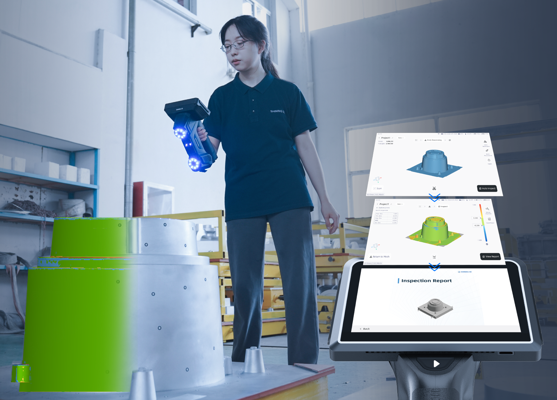
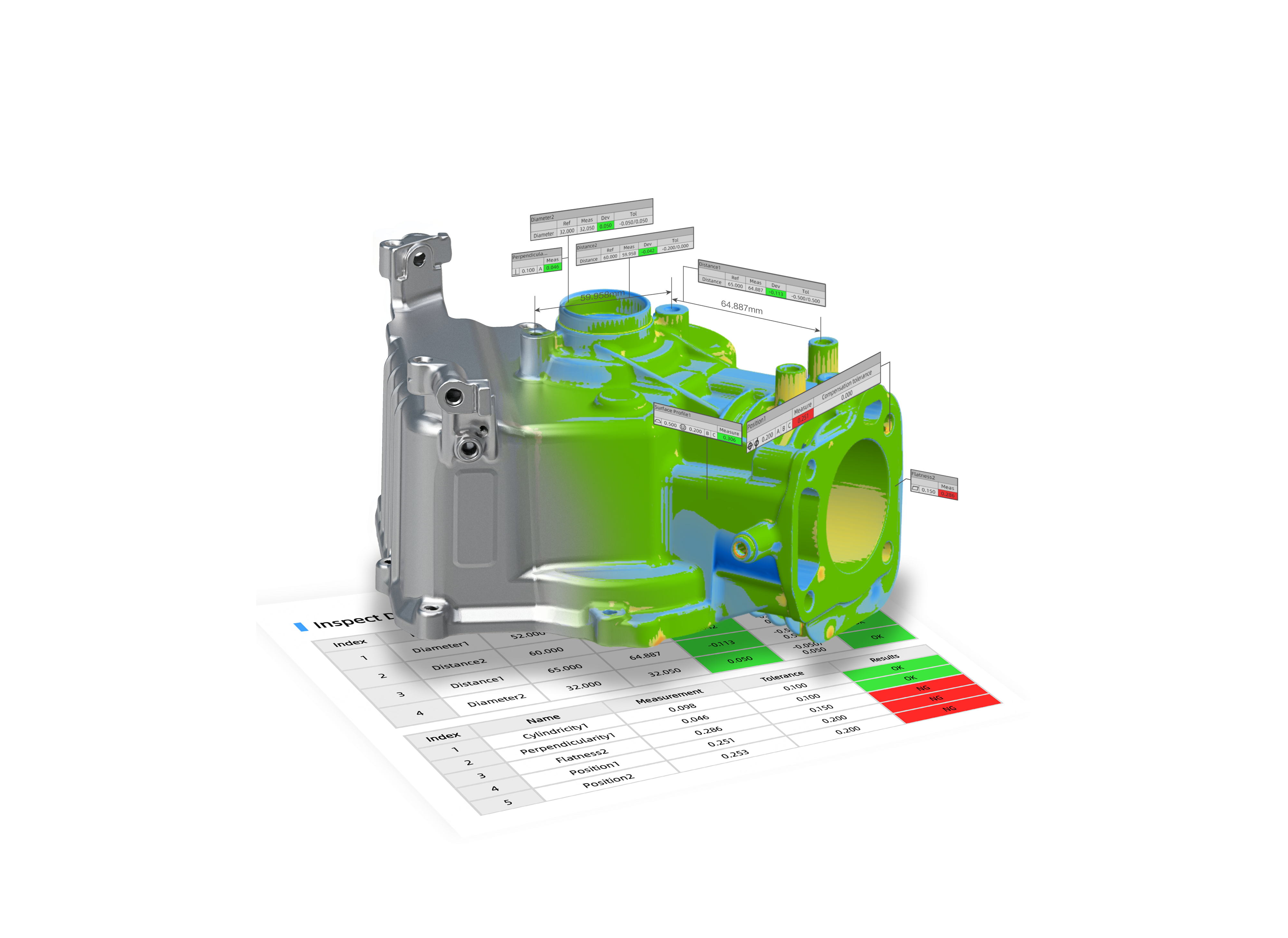
One major advantage of 3D scanning is how clearly the results can be visualized. When scan data is compared to CAD, software can generate color deviation maps that show where the part is high, low, or within tolerance.
These visual reports are easy to understand, even for people who are not metrology specialists. Engineers, quality managers, production teams, and customers can quickly see where a part differs from the CAD model.
CMM reports are often more focused on numerical results for selected dimensions and features. This is valuable for formal inspection records, but it may not always communicate the full shape of the part as clearly as a color map or full-field scan report.
For communication, troubleshooting, and process improvement, 3D scanning can make inspection results easier to interpret.
Portability and Shop-Floor Use
Traditional CMMs are often located in controlled inspection rooms because they can be sensitive to temperature, vibration, and environmental variation. This controlled environment helps ensure measurement repeatability and accuracy.
Many modern 3D scanners are portable and can be used directly on the shop floor, in a workshop, or around large parts that are difficult to move. This can be a major advantage when inspecting heavy equipment, large tooling, automotive components, aerospace parts, or installed machinery.
Portable 3D scanning allows users to bring the measurement system to the part instead of bringing the part to the measurement system. This can reduce downtime, part handling, and inspection bottlenecks.
When a CMM Is the Better Choice
A CMM may be the better choice when the part has very tight tolerances, when the inspection plan is focused on specific critical dimensions, or when the organization already has established CMM routines for production quality control.
CMMs are also a strong choice for highly repeatable inspection of machined parts, precision components, datums, holes, bores, and geometric tolerances that require controlled point-based measurement.
For many manufacturers, the CMM remains a trusted standard for final inspection, certification, and high-precision dimensional verification.
When 3D Scanning Is the Better Choice
3D scanning may be the better choice when the part has complex surfaces, when inspection speed matters, or when users need a complete digital record of the object. It is also useful when the part is too large, heavy, fragile, or inconvenient to move to a traditional inspection setup.
Scanning is especially valuable for castings, molded parts, automotive panels, aerospace components, artistic or organic shapes, reverse engineering, wear analysis, tooling verification, and first article inspection where full-surface comparison provides more insight than selected point measurement.
For users who need fast, visual, full-field inspection results, 3D scanning can offer a major workflow advantage.
Can 3D Scanning Replace a CMM?
In some workflows, yes and it will likely massively speedup those workflows as well. In others, no.
3D scanning can replace CMM inspection when the required accuracy, reporting needs, and inspection standards are well matched to the scanner and software workflow. This is increasingly common for complex parts, large parts, and applications where full-field inspection provides more value than point-based measurement.
However, CMMs still remain important for very high-precision features, established quality procedures, and inspection plans where touch-probe measurements are required. In many professional environments, the best approach is not to choose one technology permanently, but to use each where it performs best.
A practical quality control workflow may use 3D scanning for fast full-surface inspection and CMM measurement for the tightest critical features.
Final Thoughts
3D scanning and CMM inspection are both powerful measurement technologies, but they are built around different strengths. CMMs provide precise, repeatable point-based measurement for critical features and controlled inspection workflows. 3D scanners provide fast, full-field surface capture that is ideal for complex parts, large objects, visual reporting, reverse engineering, and process improvement.
For manufacturers, the best choice depends on the part and the inspection goal. If the priority is measuring a small number of tight-tolerance features, a CMM may be the best fit. If the priority is capturing the full shape of the part quickly and understanding surface variation, 3D scanning may be the better solution.
In many modern quality control environments, the strongest workflow uses both technologies together. CMMs provide trusted precision for critical dimensions, while 3D scanners provide speed, coverage, and visual insight across the entire part.